Turn on suggestions
Auto-suggest helps you quickly narrow down your search results by suggesting possible matches as you type.
Showing results for
- STMicroelectronics Community
- STM32 MCUs
- STM32 MCUs Products
- Re: How to power a STM32F746G-DISCO board from the...
Options
- Subscribe to RSS Feed
- Mark Topic as New
- Mark Topic as Read
- Float this Topic for Current User
- Bookmark
- Subscribe
- Mute
- Printer Friendly Page
How to power a STM32F746G-DISCO board from the CN6 VIN pin ?
Options
- Mark as New
- Bookmark
- Subscribe
- Mute
- Subscribe to RSS Feed
- Permalink
- Email to a Friend
- Report Inappropriate Content
2018-10-14 3:20 AM
Hi,
I'm trying to power a STM32F746G-DISCO board from the CN6 VIN pin.
I have a voltage regulator that output 11VDC current.

The screen turns on but the program never start and LD6 and LD3 become red after a few seconds.
I measured the current between GND and VIN, it's 11VDC , during few seconds, the it go down to 3.3V.
I measured the VO from the voltage regulator without connecting it to the board, and it's 11VDC stable.
The jumper is on V5ext, as explained in the documentation.
What is wrong with that setup ?
Everything works fine with USB.
16 REPLIES 16
Options
- Mark as New
- Bookmark
- Subscribe
- Mute
- Subscribe to RSS Feed
- Permalink
- Email to a Friend
- Report Inappropriate Content
2018-10-21 3:09 PM
You can't use the linear reg... and you need capacity.
" 317 is outputting 500mA," it must be burning.... 24V - 12 = 12V... @0.5A = 6 Watts
@LMI2 has shown you the DC-DC converters, they work very well.
Its advised to use inductors in series to dissipate the switching noise, refer to the datasheet.
then your board will run a bit warm.... not blazing.....
then add minimum 1000uF before the reg and something 10-100uF after.
Low ESR caps are preferred, but not always necessary.
" 317 is outputting 500mA,"
Did you damage your board already ? looks like it.. :(
are any chips blazing too ?
Options
- Mark as New
- Bookmark
- Subscribe
- Mute
- Subscribe to RSS Feed
- Permalink
- Email to a Friend
- Report Inappropriate Content
2018-10-23 12:39 PM
Hi Everyone,
So I tried with a R-78E5.0-0.5 connected directly to the 5V arduino PIN and it works great.
I also tried a with a R-78C9.0-1.0 connected to the VIN PIN, which sound more logic for me because it's a VIN pin (that should be between 7 and 12V regarding specs) but that didn't work.
I want to use arduinos pins because I printed a bread board and I don't want to use the JP1 connector.
Is it ok to power the board through the 5V arduino PIN ? The documentation doesn't list it as a possible powering connector.
Do I have to add some capacitors with the R-78E5.0-0.5 to protect the board ? The datasheet doesn't say it's necessary. But what would you do ?
I found that scheme on an other version of the R-78 :
Nicolas
Options
- Mark as New
- Bookmark
- Subscribe
- Mute
- Subscribe to RSS Feed
- Permalink
- Email to a Friend
- Report Inappropriate Content
2018-10-23 3:44 PM
Yes, you can run the boards from the USB power.
Good work... !
So the on board regulator is not coping... hence the need for the Recom 5V unit...
I am not sure why the 7-12V didnt work.
did you add some parts to the board ?
Options
- Mark as New
- Bookmark
- Subscribe
- Mute
- Subscribe to RSS Feed
- Permalink
- Email to a Friend
- Report Inappropriate Content
2018-10-24 3:39 AM
No, I plugged the R-78x directly to the DISCO board, without any other parts.
It cost me one board because of a wrong plug (9v --> 5v arduino pin) :). But now I know I have to be very carefull. Also, I can't use USB port while the board is powered by 5V pin, but I will deal with that.
Is it recommended to add 10uF capacitors with the R-78E5.0-0.5 ? It work fine without, but I saw on some posts it was recommended with other DC/DC converters.
Options
- Mark as New
- Bookmark
- Subscribe
- Mute
- Subscribe to RSS Feed
- Permalink
- Email to a Friend
- Report Inappropriate Content
2018-11-16 1:16 PM
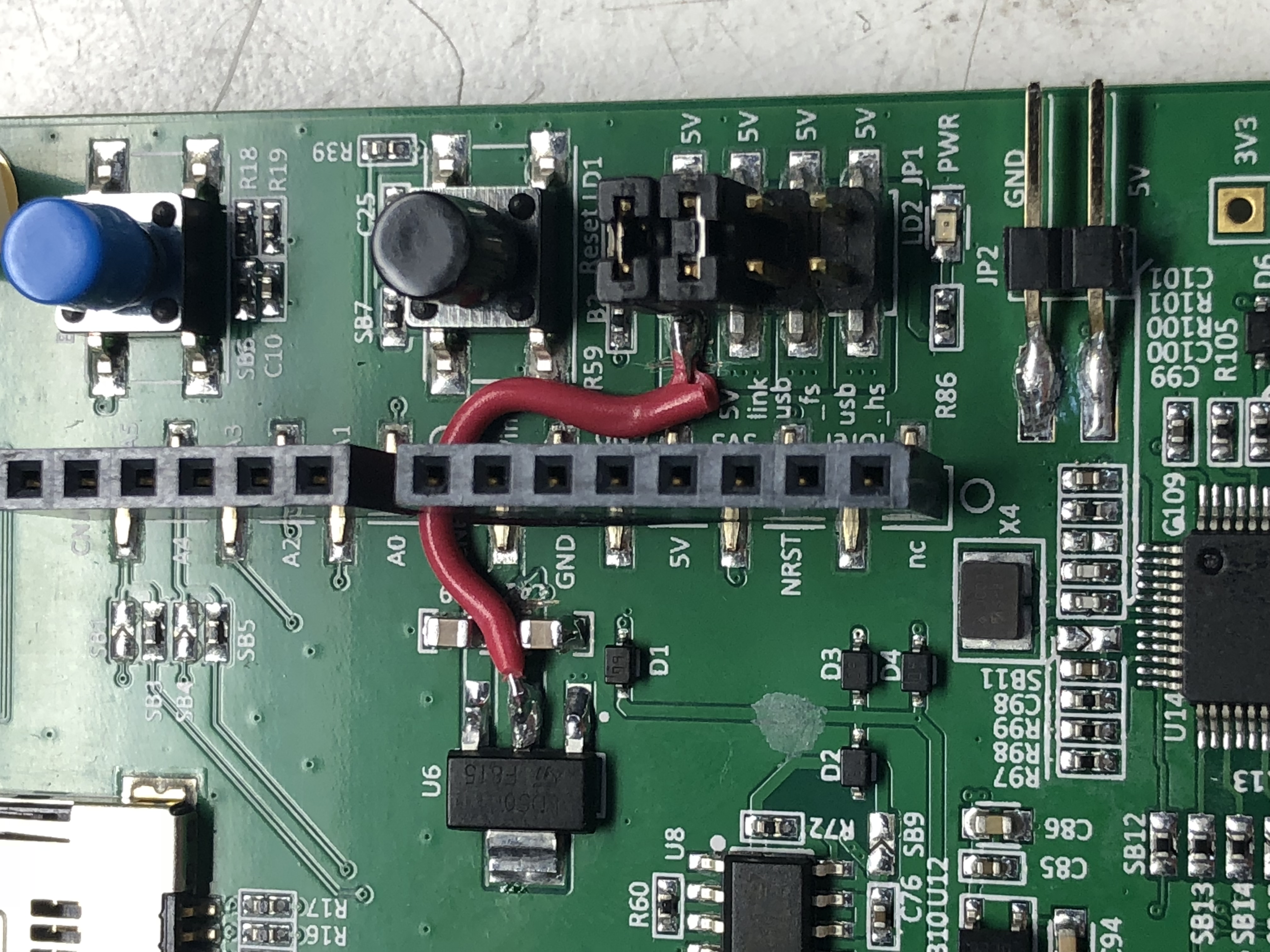
Not sure if anyone else has run into my issue, but this seemed like a good place to post it since it's somewhat related and I landed here while looking for answers.
I was having very similar problems using the "VIN" pin on the Arduino header. I have two of these STM32F746G-Disco boards and they both had the same problem... The V-Out pin on U6 (5V reg) was shorted directly to ground (in the PCB, even after removing components).
A little board modification to cut the connection at both ends and route a new wire over to the jumper header and now they both work perfectly.
Maybe there's something else I missed somewhere and someone here can point that out, but this did the trick for me. I hope it can help someone else =)


- « Previous
-
- 1
- 2
- Next »
Related Content
- Can't connect to bootloader with UART using reset. in STM32 MCUs Boards and hardware tools
- Custom Board USB HS STM32H7S3 in STM32 MCUs Products
- STM32Cube Does Not Work After Formatting the Computer in STM32CubeIDE (MCUs)
- Unable to Connect to STM32H747 After Flashing Code in CubeIDE in STM32CubeIDE (MCUs)
- STM32f407vgt6 stlink v2 not connecting on PCB in STM32 MCUs Boards and hardware tools