JTurn.2
Associate III
October 17, 2021
Solved

Clarification about connecting UART and SPI to the STMod+

  • October 17, 2021
  • 3 replies
  • 1808 views

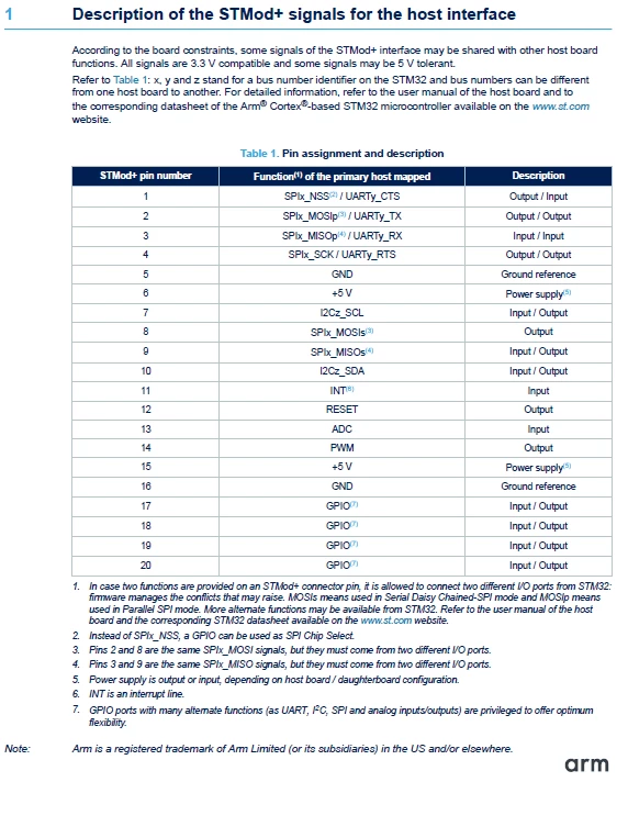
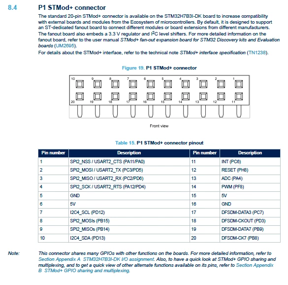
I am trying to connect an SPI communication device and a UART communication device to my STM32H7B3I-DK using the STMod+. From the datasheet for the discovery board, SPI and UART use the same lines (pin numbers 3 and 4) to connect the connections on the STMod+ to the discovery board. But then after reading the datasheet for the STMod+, it says that pins 2 and 8, and pins 3 and 9 are the same? This is where I'm a bit confused. So here are my questions:

  1. If I want enable SPI2 only or UART2 only, do I just set this by disabling the one that I don't need in ST32MXCUBE?
  2. If I want to use both SPI2 and UART2, do I connect the UART device to 2 and 3 and use pins 8 and 9 for the SPI device?
  3. Do I assume that the UART for the connector esp-01 (CN4) and the connector CN10 on the STMod+ are the same so I can only use one of them at any moment?

I have attached screenshots of the datasheets I'm referring to below. Thank you very much for your help!0693W00000FCmnPQAT.png0693W00000FCmnKQAT.png
This topic has been closed for replies.
Best answer by S.Ma

The STMod+ pin 1..4 are the prime pins for Usart xor SPI interfaces. Optionally, if the mcu allows and if only simple 2 wire uart is used, uart and spi can be formed with rx tx using pin 2 and 3, while SPI are using pin 1, 4, 8 and 9. The mcu can output the same peripheral signals on different pins. The I2C bus using pin 7 and 10. The connector is 2mm pitch simple mix of PMOD, Click and Seed grove connectors which extend the ecosystem from Arduino on the Fan out board.

3 replies

S.Ma
S.MaBest answer
Principal
October 17, 2021

The STMod+ pin 1..4 are the prime pins for Usart xor SPI interfaces. Optionally, if the mcu allows and if only simple 2 wire uart is used, uart and spi can be formed with rx tx using pin 2 and 3, while SPI are using pin 1, 4, 8 and 9. The mcu can output the same peripheral signals on different pins. The I2C bus using pin 7 and 10. The connector is 2mm pitch simple mix of PMOD, Click and Seed grove connectors which extend the ecosystem from Arduino on the Fan out board.

S.Ma
Principal
October 17, 2021

Also some newer gen usart IP have RX TX swap functions.

JTurn.2
JTurn.2Author
Associate III
October 18, 2021

I see. Thank you for your clarification!