Turn on suggestions
Auto-suggest helps you quickly narrow down your search results by suggesting possible matches as you type.
Showing results for
- STMicroelectronics Community
- STM32 MCUs
- STM32 MCUs Boards and hardware tools
- Voltage Stacking with energy harvesting STM32WB55
Options
- Subscribe to RSS Feed
- Mark Topic as New
- Mark Topic as Read
- Float this Topic for Current User
- Bookmark
- Subscribe
- Mute
- Printer Friendly Page
Voltage Stacking with energy harvesting STM32WB55
Options
- Mark as New
- Bookmark
- Subscribe
- Mute
- Subscribe to RSS Feed
- Permalink
- Email to a Friend
- Report Inappropriate Content
2025-02-25 3:46 AM - edited 2025-02-25 6:22 AM
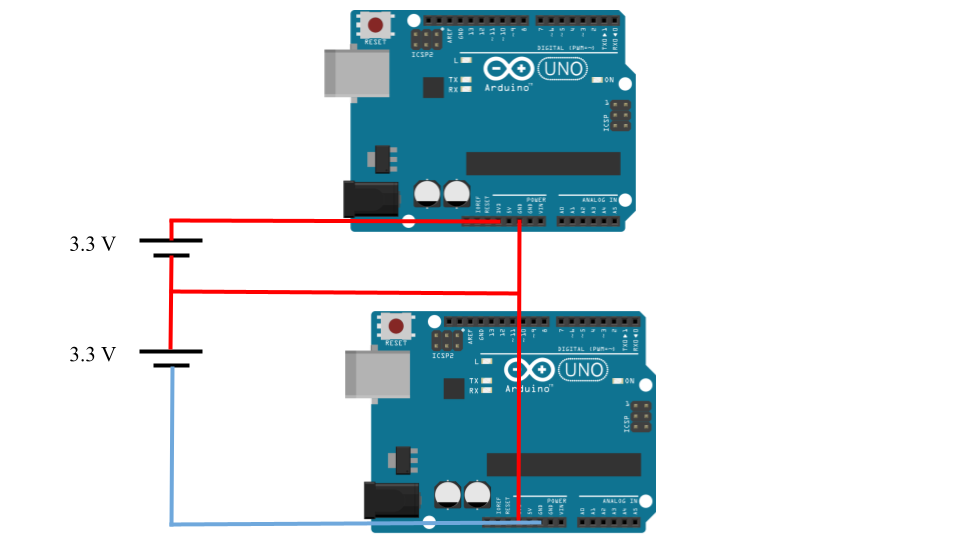
Hello, I am attempting in voltage stacking of 2 STM32WB55 board, but unlike arduino I could not connect Top board's GND to bottom board's 3.3 V pin. I would like to request for help or insights for alternative method I could make it work. I would really appreciate the help.
Problem
1. When I connect the Top STM32 GND to the VDD of Btm STM32, it discharged the voltage in Btm capacitor.
2. On one attempt I rearranged the circuit in similar stacked configuration, it did not discharged the Btm capacitor voltage. Instead the system goes haywire.
Thank you.

Labels:
- Labels:
-
Other boards
-
Power
-
Schematic
-
ST boards
12 REPLIES 12
Options
- Mark as New
- Bookmark
- Subscribe
- Mute
- Subscribe to RSS Feed
- Permalink
- Email to a Friend
- Report Inappropriate Content
2025-02-25 3:49 AM - edited 2025-02-25 4:09 AM
Options
- Mark as New
- Bookmark
- Subscribe
- Mute
- Subscribe to RSS Feed
- Permalink
- Email to a Friend
- Report Inappropriate Content
2025-02-25 3:54 AM
Sorry for being unclear, I had attached a image that I had drawn for better explanation of my issue.
Options
- Mark as New
- Bookmark
- Subscribe
- Mute
- Subscribe to RSS Feed
- Permalink
- Email to a Friend
- Report Inappropriate Content
2025-02-25 4:10 AM
Thanks for adding the diagram - these things are so often better described by a diagram than in words.
But some more detail is required:
- How, exactly, did you connect the boards together?
Please provide a schematic.
- What problem(s), exactly, did you encounter?
Also, what is the purpose of connecting the boards like that anyhow?
Why not just have them separate, or in parallel?

Options
- Mark as New
- Bookmark
- Subscribe
- Mute
- Subscribe to RSS Feed
- Permalink
- Email to a Friend
- Report Inappropriate Content
2025-02-25 4:30 AM
This is my research topic for my bachelor degree. I am attempting on a power management method called voltage stacking, it is commonly used on transistor level design. The advantage of doing voltage stacking or in series arrangement is the reduction of current demand of each domain that are stacked, following V = IR.
My goal is to find out that in an energy harvesting system, could I achieve what is observed on transistor level if I attempt voltage stacking, which is halving of current demand or 1/n where n is the number of stacked layers. I had tried out the parallel arrangement and observed the data but I faced problem when trying to connect them in series.
1. When I connect the Top STM32 GND to the VDD of Btm STM32, it discharged the voltage in Btm capacitor.
2. On one attempt I rearranged the circuit in similar stacked configuration, it did not discharged the Btm capacitor voltage. Instead the system goes haywire.
I attempt voltage stacking with arduino initially I had attached the image below, I know it looks disturbing or obnoxious but with this I could observe a near halving of current demand compare to conventional parallel arrangement. Currently, is that I would like to replicate similar result with STM32 boards.

Options
- Mark as New
- Bookmark
- Subscribe
- Mute
- Subscribe to RSS Feed
- Permalink
- Email to a Friend
- Report Inappropriate Content
2025-02-25 4:57 AM
But microcontroller boards aren't just simple resistive devices that you can connect in series, and apply Ohm's law.
They contain voltage regulators, and other non-linear stuff.
Current consumption is discontinuous, and the two boards will not be drawing the same current at the same time.
@methene wrote:The advantage of doing voltage stacking or in series arrangement is the reduction of current demand of each domain that are stacked,
I don't see how your arrangement achieves that:

.drawio.png)
This is not a series connection!
Options
- Mark as New
- Bookmark
- Subscribe
- Mute
- Subscribe to RSS Feed
- Permalink
- Email to a Friend
- Report Inappropriate Content
2025-02-25 5:14 AM - edited 2025-02-25 5:14 AM
Yes, you are absolutely correct it is not exactly a series connection, but I am doing the connection arrangement based on my readings in literature review on voltage stacking. I had attached 2 of them for you review. The current of the 2 boards are not exactly the same but it should have been halved compared to conventional ones.
With the link you sent, are you suggesting that it is impossible to arrange STM32WB board in in the configuration of my sketch?
Options
- Mark as New
- Bookmark
- Subscribe
- Mute
- Subscribe to RSS Feed
- Permalink
- Email to a Friend
- Report Inappropriate Content
2025-02-25 6:12 AM
@methene wrote:The current of the 2 boards are not exactly the same but it should have been halved compared to conventional ones.
But, if they are in series, they must - by definition - be the same. They cannot be different.
You would have to make some sort of shunt regulator, which would largely - if not entirely - defeat the object!
Options
- Mark as New
- Bookmark
- Subscribe
- Mute
- Subscribe to RSS Feed
- Permalink
- Email to a Friend
- Report Inappropriate Content
2025-02-25 6:26 AM
Ouh sorry, what I meant was they are not "exactly" the same but very similar, as you mentioned by definition it should be the same. And this can be observed when I did my arduino testing experiment of voltage stacking.
Currently my problem faced would be that how can I connect the pins of STM32WB55 board with the capacitor to achieve similar result that I had obtained with arduino voltage stacking.
Options
- Mark as New
- Bookmark
- Subscribe
- Mute
- Subscribe to RSS Feed
- Permalink
- Email to a Friend
- Report Inappropriate Content
2025-02-25 6:40 AM
Again, see:
The boards are simply not designed to work in this way.
If you really want to pursue this, you're going to have to do a custom board design which is specifically designed for this. Even that is likely a dead-end, as the chips themselves have not been designed for this.
If you're interested in maximising energy harvesting, I would suggest that you look into switched-mode power supplies, and Maximum Power Point Tracking (MPPT)...
Related Content