Turn on suggestions
Auto-suggest helps you quickly narrow down your search results by suggesting possible matches as you type.
Showing results for
- STMicroelectronics Community
- Product forums
- Power management
- Re: T810-600B-TR TRIAC Not Turning ON With Load
Options
- Subscribe to RSS Feed
- Mark Topic as New
- Mark Topic as Read
- Float this Topic for Current User
- Bookmark
- Subscribe
- Mute
- Printer Friendly Page
T810-600B-TR TRIAC Not Turning ON With Load
Options
- Mark as New
- Bookmark
- Subscribe
- Mute
- Subscribe to RSS Feed
- Permalink
- Email to a Friend
- Report Inappropriate Content
2023-08-28 01:49 PM - last edited on 2023-08-31 12:31 AM by Peter BENSCH
I have a legacy project that I converted to an SMT design but the existing TRIAC is not meeting all specifications of the product. I am evaluating other options and one option that I'm looking at is the T810-600B-TR. In this application, the transistor is fully turned ON and passes 120VAC for up to 12ish minutes, then turns OFF. I have played around and can't get this part to fully turn on under load. The gate is drawing 14mA, gate voltage is 0.9V but the output is only 62VAC under a 500W load. However, when there is no load, the output is 117VAC.
Why wouldn't I be able to get this part to pass all of the input when it is under load?
Labels:
- Labels:
-
Discretes
14 REPLIES 14
Options
- Mark as New
- Bookmark
- Subscribe
- Mute
- Subscribe to RSS Feed
- Permalink
- Email to a Friend
- Report Inappropriate Content
2023-08-28 02:10 PM
make a DSO pic, trace 1 : gate current , trace 2: anode voltage. to see, when and how much gate current is at the triac. (2x , pos and neg trigger )
If you feel a post has answered your question, please click "Accept as Solution".
Options
- Mark as New
- Bookmark
- Subscribe
- Mute
- Subscribe to RSS Feed
- Permalink
- Email to a Friend
- Report Inappropriate Content
2023-08-30 09:40 AM
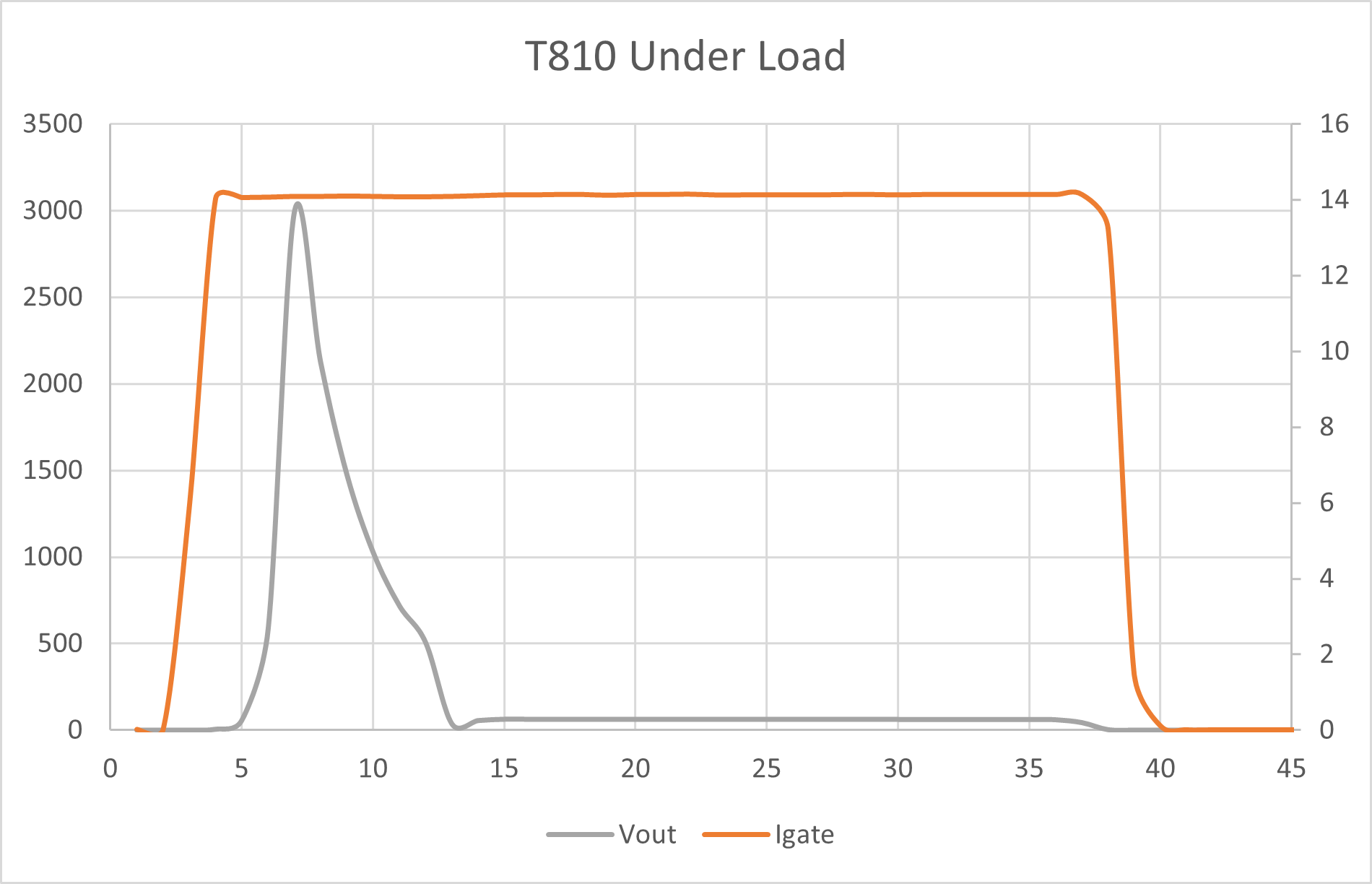
Unfortunately I don't have an isolation transformer yet. So I'm not able to measure the Vout with the scope. The best I was able to do with the equipment I have was to log a couple of hand held DMMs that have isolated serial ports, then plot the data in excel. It is very strange though because the Vout jumps up beyond the VAC rating but that must have been some weird glitch. I have the graph that I generated from the data attached.
Options
- Mark as New
- Bookmark
- Subscribe
- Mute
- Subscribe to RSS Feed
- Permalink
- Email to a Friend
- Report Inappropriate Content
2023-08-30 12:25 PM - edited 2023-08-30 12:26 PM
you made a nice picture, but no scale, no value, so sorry, but talking about pictures will help nobody.
if you cannot make any real time measurement, nothing real to talk about.
If you feel a post has answered your question, please click "Accept as Solution".
Options
- Mark as New
- Bookmark
- Subscribe
- Mute
- Subscribe to RSS Feed
- Permalink
- Email to a Friend
- Report Inappropriate Content
2023-08-30 01:39 PM
Options
- Mark as New
- Bookmark
- Subscribe
- Mute
- Subscribe to RSS Feed
- Permalink
- Email to a Friend
- Report Inappropriate Content
2023-10-04 10:14 AM - edited 2023-10-04 11:13 AM
Ok, I picked up an isolation transformer and grabbed some real time captures on the DSO.
Under load, the top half of the sine wave doesn't get passed.
Edit:
Nevermind... Removed pictures, I need to go back to get new measurements. I see that AC is passing regardless of gate drive.
Options
- Mark as New
- Bookmark
- Subscribe
- Mute
- Subscribe to RSS Feed
- Permalink
- Email to a Friend
- Report Inappropriate Content
2023-10-04 11:51 AM
Options
- Mark as New
- Bookmark
- Subscribe
- Mute
- Subscribe to RSS Feed
- Permalink
- Email to a Friend
- Report Inappropriate Content
2023-10-04 12:13 PM
show circuit . and where your test points are, for trace 1 + 2 .
somewhere is a cap at the gate/trigger drive , that shifts dc level for trigger.
If you feel a post has answered your question, please click "Accept as Solution".
Options
- Mark as New
- Bookmark
- Subscribe
- Mute
- Subscribe to RSS Feed
- Permalink
- Email to a Friend
- Report Inappropriate Content
2023-10-10 10:18 AM
Options
- Mark as New
- Bookmark
- Subscribe
- Mute
- Subscribe to RSS Feed
- Permalink
- Email to a Friend
- Report Inappropriate Content
2023-10-10 10:39 AM
Mmmm . this is no good circuit for a triac . there are many couplers, to this job, ie. MOC3083 or similar.

with input current > 5mA (from your timer controlled circuit -> transistor out) this "MOCxxx" generates at zero crossing start pulse for triac - reliable. and low emission on mains...because zero crossing switching.
change your circuit...
If you feel a post has answered your question, please click "Accept as Solution".
Related Content
- Running code without debugging (SR5E1-EVBE7000P) in Automotive MCUs
- Can we at least have an option to turn off the dark overlay of BGA top view in STM32CubeMX (MCUs)
- eMMC in STM32H745I-Disco in STM32 MCUs Products
- STM32WL55 Using LPUART in STOP2 mode with wake-up & clock-switching (HSI-MSI) in STM32 MCUs Wireless
- Power turn ON and Power turn OFF detection. in STM32 MCUs Products