Turn on suggestions
Auto-suggest helps you quickly narrow down your search results by suggesting possible matches as you type.
Showing results for
- STMicroelectronics Community
- Product forums
- Power management
- SPV1040T Not Working as intended.
Options
- Subscribe to RSS Feed
- Mark Topic as New
- Mark Topic as Read
- Float this Topic for Current User
- Bookmark
- Subscribe
- Mute
- Printer Friendly Page
SPV1040T Not Working as intended.
Options
- Mark as New
- Bookmark
- Subscribe
- Mute
- Subscribe to RSS Feed
- Permalink
- Email to a Friend
- Report Inappropriate Content
2024-03-26 03:11 AM
Hello,
I'm trying to use the SPV1040T MPPT IC to boost up the 1.5V I'm getting from the Solar Panel to 3.8V. When I Power ON the MPPT IC its output just follows the Input and i don't see any chances of voltage getting boosted up. Is there anything wrong in the design attached? Please advise.
For now, I'm using the Lab power supply to power the MPPT IC, the O/P voltage is set to 1.5V, Current limit is set to 100mA.
Regards
Stalin
Labels:
- Labels:
-
Power Supply Management
17 REPLIES 17
Options
- Mark as New
- Bookmark
- Subscribe
- Mute
- Subscribe to RSS Feed
- Permalink
- Email to a Friend
- Report Inappropriate Content
2024-03-26 03:39 AM
Hi,
from ds:


So connect the ictrl-xx to gnd, and xshut to PV+.
If you feel a post has answered your question, please click "Accept as Solution".
Options
- Mark as New
- Bookmark
- Subscribe
- Mute
- Subscribe to RSS Feed
- Permalink
- Email to a Friend
- Report Inappropriate Content
2024-03-27 05:15 AM
Thanks for the Suggestion.
I did the Following modifications today and captured the I/P and O/P waveforms. Can you check if anything still wrong to get the desired output voltage of 3.8V?
The Measurements are done with No load attached to the output of the MPPT IC.
Options
- Mark as New
- Bookmark
- Subscribe
- Mute
- Subscribe to RSS Feed
- Permalink
- Email to a Friend
- Report Inappropriate Content
2024-03-27 10:59 AM
So its working now . good !
Seems it going to "skip mode" , doing some pulses, get much voltage and stops for safety , until it tries again.
To test this, give it some load (resistor to gnd, to get about the target current, you want) + maybe a bigger load cap (470uF or so); you have to try, i dont have this chip. (So i just can tell from my experience with other smps chips.)
+ the diode CR14 should be there.
If you feel a post has answered your question, please click "Accept as Solution".
Options
- Mark as New
- Bookmark
- Subscribe
- Mute
- Subscribe to RSS Feed
- Permalink
- Email to a Friend
- Report Inappropriate Content
2024-03-28 03:18 AM
Appreciate your comments.
I tried to add 500uF CAP at the output of the MPPT and connected the output to an Electronic Load (Constant Resistance mode) and varied the Load resistance.
Looks the MPPT is now operating in the continuous conduction mode but, it doesn't look the desired output voltage is achieved yet.
Options
- Mark as New
- Bookmark
- Subscribe
- Mute
- Subscribe to RSS Feed
- Permalink
- Email to a Friend
- Report Inappropriate Content
2024-03-28 10:48 AM
Can you show a pic of the test setup you work on?
+ the board layout .
Seems there are big switching spikes...this could prevent correct working.
If you feel a post has answered your question, please click "Accept as Solution".
Options
- Mark as New
- Bookmark
- Subscribe
- Mute
- Subscribe to RSS Feed
- Permalink
- Email to a Friend
- Report Inappropriate Content
2024-04-01 09:19 AM
Sure. Test Setup and PCB Layout attached FYR.
I couldn't attach the PCB layout (.brd file) because the file format doesn't allow me to attach here.
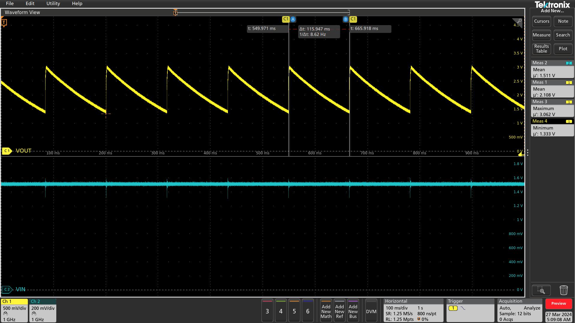
Instead of the Resistive load I also tried connecting the actual Load (Super CAP- 2.5F) into the MPPT with the Current limiting Resistor 63ohms. The Input & Output waveforms look like below.
Options
- Mark as New
- Bookmark
- Subscribe
- Mute
- Subscribe to RSS Feed
- Permalink
- Email to a Friend
- Report Inappropriate Content
2024-04-02 04:10 AM
So - nice scope . :)
+ pic on scope : really in + out ?? (looks like almost a short in->out )
Because almost same signal (and you have better ground now, signals themselves looking fine now.)
Sure you have diode CR14 not reversed connected ? (or try without diode, what happens then?)
Basically the chip switching now at about 100kHz , what it should do. ok , so far.
But anyway input seems to pull too much current (for your target power), i would try L -> 68...100uH (about) ,
and as input a simple AA cell, (1.5V ) , to avoid any strange limiting action from the regulated supply .
If you feel a post has answered your question, please click "Accept as Solution".
Options
- Mark as New
- Bookmark
- Subscribe
- Mute
- Subscribe to RSS Feed
- Permalink
- Email to a Friend
- Report Inappropriate Content
2024-04-03 08:18 AM
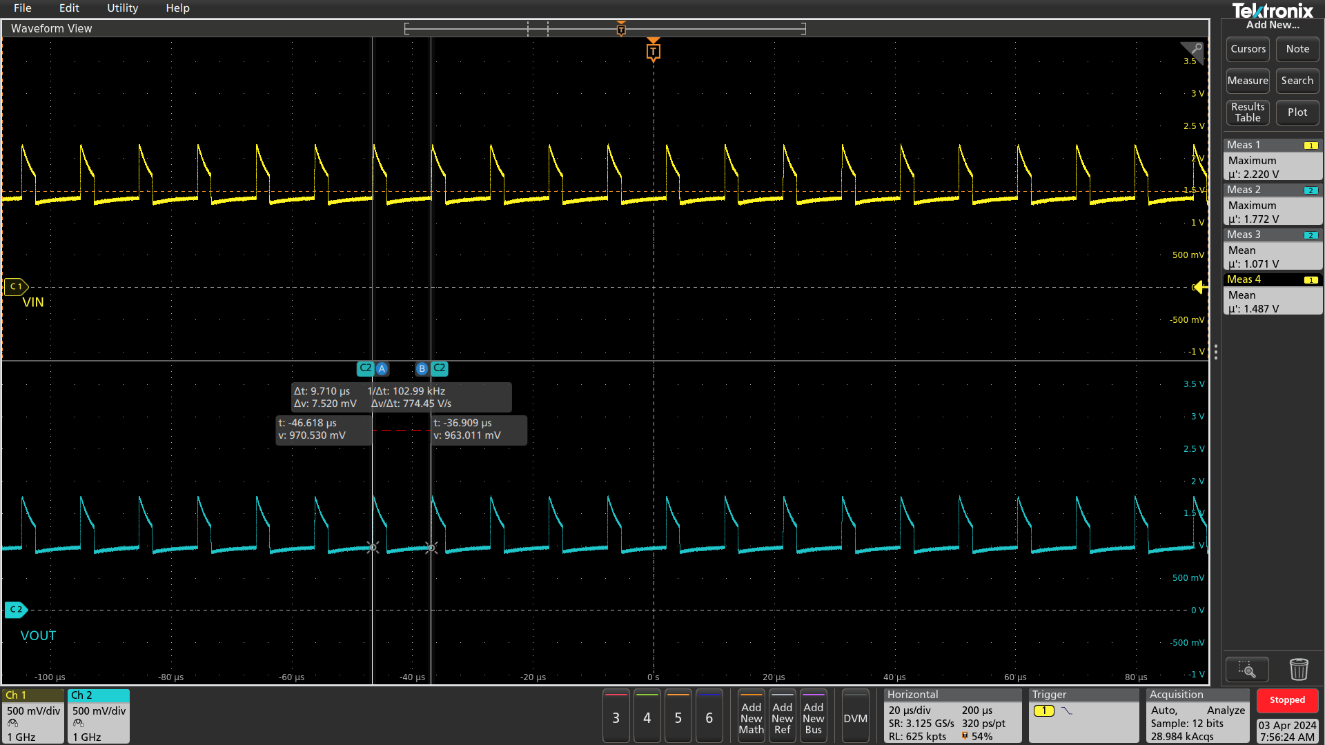
I removed the diode, and the scope plots looks little different than before. I also tried to change the inductor value from 10uH to 33uH (that's the highest I can find quickly) not many improvements other than slight changes in the waveforms.
FYI - the VIN was probed at the Inductor Pin that connects to the Pin No 3 (LX) of the MPPT IC.
I'm suspecting if any problem in the Voltage regulation loop. I will try to change the resistor value to match with the STEVAL-ISV006V2 Evaluation board. The Values I used seems much lower than the evaluation board.
Options
- Mark as New
- Bookmark
- Subscribe
- Mute
- Subscribe to RSS Feed
- Permalink
- Email to a Friend
- Report Inappropriate Content
2024-04-03 08:33 AM
Sorry, but still in almost same as output -> chip damaged ??
+
output has sharp rising and falling signal = impossible with low impedance caps > 10uF there !
So check, are the caps really there and have contact to gnd (-plane) .
If you feel a post has answered your question, please click "Accept as Solution".
Related Content
- How to Dynamically Change Flash Base Address for OTA Updates Without Hardcoding in Bin File? in STM32 MCUs Products
- Block Erase Function Issue with MT25QL01GBBB NOR Flash on STM32 MCU in STM32 MCUs Products
- USB HID: how to send more than 64 bytes of data (host-to-device)? in STM32 MCUs Products
- STM32WB HAL + Bluetooth disables periodic RTC wakeup interrupt in STM32 MCUs Wireless
- STM32 USB HID - more buttons problem (button box / joystick buttons) in STM32 MCUs Products