Turn on suggestions
Auto-suggest helps you quickly narrow down your search results by suggesting possible matches as you type.
Showing results for
- STMicroelectronics Community
- Product forums
- Other: hardware
- STPM34 shunt measuring
Options
- Subscribe to RSS Feed
- Mark Topic as New
- Mark Topic as Read
- Float this Topic for Current User
- Bookmark
- Subscribe
- Mute
- Printer Friendly Page
STPM34 shunt measuring
Options
- Mark as New
- Bookmark
- Subscribe
- Mute
- Subscribe to RSS Feed
- Permalink
- Email to a Friend
- Report Inappropriate Content
2024-06-08 12:29 PM
Hi everybody,
I made a circuit for the STPM34, but I keep destroying my components 🙂
The first image is what my circuit looks like, I followed the datsheet closely, yet there seems to be a mistake somewhere.
I've noticed it goes wrong at my current measuring circuit, namely the 1k resistors burn and the STPM34 explodes.
Between the shunt and the pins IIP1 and IIN1 I measure 1kOhm, as it should be.
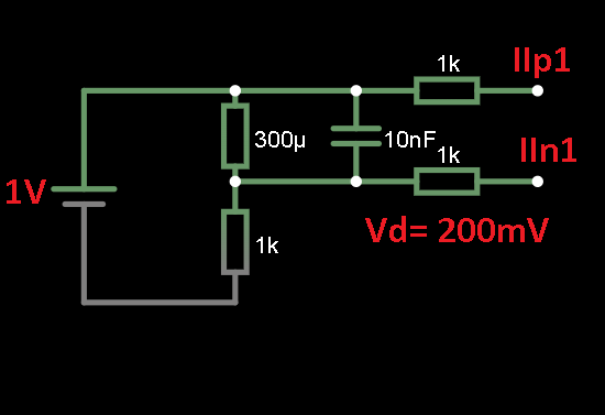
I made a quick test setup with a 1V DC supply, and noticed the voltage drop over the 1kOhm resistor is way too high (200mV). The setup of this test circuit is shown in the notes.
The orientation of the IC is correct, so I'm connected to the right pins.
Any ideas what may be the cause for this high voltage drop?
Labels:
- Labels:
-
Legacy Products
2 REPLIES 2
Options
- Mark as New
- Bookmark
- Subscribe
- Mute
- Subscribe to RSS Feed
- Permalink
- Email to a Friend
- Report Inappropriate Content
2024-06-09 12:17 AM
The current needs to controlled, as per your 2nd circuit, the current is just 1ma(ohm's law). So it can't create 200mv. Please check the resistors. The current is always determined by the load.
Options
- Mark as New
- Bookmark
- Subscribe
- Mute
- Subscribe to RSS Feed
- Permalink
- Email to a Friend
- Report Inappropriate Content
2024-06-09 02:27 AM - edited 2024-06-09 02:29 AM
Hi,
just i cannot find my big blue crystal ball...
so tell me: hi-side voltage? , max. supply voltage?, same gnd level ? , voltage at current-test resistor ?.
+ full circuit.
If you feel a post has answered your question, please click "Accept as Solution".
Related Content
- STPM34 DC offsets failed to be measured after all HPFs were disabled. in Other: hardware
- STPM34 (EVALSTPM34) - After HPF is disabled, why did we failed to read the V-I channel's DC offset of V / C channels? in Other: hardware
- STEVAL-CTM006V91 3-shunts current measurement. in STM32 MCUs Motor control
- Stop command and startup with Hall sensors in STM32 MCUs Motor control