Join conversations with your peers and ST experts. Explore the full potential of STM32 microcontrollers for your embedded design.
Most recent activity
Dear ST Team, I am currently working on a 24V @ 1.5A sensorless BLDC motor control application using the following setup: MCU Board: Nucleo-F401RE Driver Board: X-NUCLEO-IHM16M1 Motor: Sensorless BLDC MotorSoftware Tools: MC Workbench 6.4.0 and Motor Pilot Control Technique: Field-Oriented Control (Sensorless) Issues Observed: During startup, the motor produces loud noise, initial jerks, and fault indications in the IHM16M1 board. At higher RPMs, a mild humming noise is audible. When decreasing the speed to medium or lower RPMs, the IHM16M1 board triggers faults again in the IHM16M1 board. We have profiled the motor multiple times using Motor Pilot, and each profiling run gave slightly different values for parameters such as Friction, Inertia, and Back-EMF constant. To address this, we tested the system using the average, minimum, and maximum values obtained from multiple profiles. However, the same issues persisted across all
I'm trying to understand the operation of the STM32F446xx family of microcontrollers. I'm reading the reference manual that's available here: https://www.st.com/resource/en/reference_manual/rm0390-stm32f446xx-advanced-armbased-32bit-mcus-stmicroelectronics.pdf. I'm struggling to understand the timing of how the FMC SDRAM controller reads the data it anticipates and stores them in the FIFO. I have the following questions: 1. On page 313, in the description of the RPIPE bits, it is stated, "These bits define the delay, in KCK_FMC clock cycles, for reading data after CAS latency." Which clock does KCK_FMC refer to? And how are KCK_FMC and SDCLK related? I couldn't find KCK_FMC mentioned anywhere else in the manual. 2. On page 306, it is stated, "The FMC SDRAM controller features a Cacheable read FIFO (6 lines x 32 bits). It is used to store data read in advance DURING the CAS latency period and the RPIPE delay ..." I'm confused as to how data is read DURING the CAS latency
Hi everyone,I'm working with an STM32U5 and using USBX with the CDC-ACM class.My setup is as follows:I have a USBX CDC ACM receive thread that calls usbx_cdc_acm_read_thread_entry() in ux_device_cdc_acm.c file.Alongside, I have a state machine running in another context (main loop).If the device stays idle (no USB activity) for a certain timeout, the state machine puts the MCU into Sleep Mode using:HAL_SuspendTick();HAL_PWR_EnterSLEEPMode(PWR_LOWPOWERREGULATOR_ON, PWR_SLEEPENTRY_WFI);HAL_ResumeTick();The goal is to wake up the MCU only when data is received on the USB.To achieve this, I tried relying on USB interrupts:OTG_FS_IRQn is enabled in NVIC.The USB OTG FS peripheral is initialized properly via HAL_PCD_Init().OTG_FS_IRQHandler() is defined and calls HAL_PCD_IRQHandler()But I'm not getting out from the Sleep mode, I'm completely stuck and running out of ideas. Any assistance would be greatly appreciated. Thank you!
Split from this thread as it has been solved, and this is a new question: How to access eMMC through OTG on STM32H750B-DK kit.?
Hi, I'm searching for more details on STM32F303 ADC Voltage Regulator Function ADVREG. According AN4195 it needs to be enabled before ADC calibration. ADC Regulator is by default disabled. But i cannot see any big difference on ADC conversion results bettween enabled and default (disabled) state of the regulator. I'm using recommended ADVREG enable sequence 10 -> 00 > 01. Thanks!
Hi Team,we are currently developing a product using the STM32U5 series. In our previous version, we used the STM32U5A5VJT6Q, and for size optimization, we have migrated to the STM32U5A5QJI6Q. Both MCUs are functionally similar, and we have updated the pin configurations accordingly. We are successfully reading data from a radar sensor using the new MCU. However, we are facing an issue where the RTOS thread does not stop properly, and the record number reaches its maximum count. Upon comparing the old and new firmware, we noticed that the Configure the Systick function is present in the old version but missing in the new one. We suspect that the absence of this function might be causing the RTOS timing issues. We also found a similar unresolved query on the ST Community forum from 2018 regarding CubeMX and SysTick behavior(CubeMX and SysTick - STMicroelectronics Community). Could you please confirm: If so, what is the recommend
... leads to "funny" results:STM32L011 with 16 kB of flash, HAL inits and LED toggle in main, DEBUG, no optimization:93% of flash usedI had not expected it to be that bad! :grinning_face_with_sweat:Okay, I will probably not use too much HAL, will use Release version with optimization,but I better select an L01 in the next bigger QFN package (4x4) to get 32 kB of flash.
Hi,We're faced to a problem when dealing with LSE clock to handle RTC backup using a supercapa connected to the VBAT pin. The LSE configuration under STM32CubeIDE: The Clock Configuration function:void SystemClock_Config(void) { RCC_OscInitTypeDef RCC_OscInitStruct = {0}; RCC_ClkInitTypeDef RCC_ClkInitStruct = {0}; /** Configure LSE Drive Capability */ HAL_PWR_EnableBkUpAccess(); __HAL_RCC_LSEDRIVE_CONFIG(RCC_LSEDRIVE_LOW); /** Initializes the RCC Oscillators according to the specified parameters * in the RCC_OscInitTypeDef structure. */ RCC_OscInitStruct.OscillatorType = RCC_OSCILLATORTYPE_HSI|RCC_OSCILLATORTYPE_LSI1 |RCC_OSCILLATORTYPE_HSE|RCC_OSCILLATORTYPE_LSE; RCC_OscInitStruct.HSEState = RCC_HSE_ON; RCC_OscInitStruct.LSEState = RCC_LSE_ON; RCC_OscInitStruct.HSIState = RCC_HSI_ON; RCC_OscInitStruct.HSICalibrationValue = RCC_HSICALIBRATION_DEFAULT; RCC_OscInitStruct.LSIState = RCC_LSI_ON; RCC_OscInitStruct.PLL.PLLState = RCC_PLL_NONE; if (HA
hello.I am using STM32F407VGT6 chip and trying to send data to PC with USB CDC function.But in the below function, the TrySendUsbPacket() function is not executing due to queue full phenomenon.void EnqueueUsbPacket(const uint8_t* data) { uint16_t next_tail = (usb_queue_tail + 1) % USB_QUEUE_SIZE; if (next_tail == usb_queue_head) { // Queue full: handle accordingly (error, framedrop, etc.) return; } memcpy((void*)usb_queue[usb_queue_tail].data, data, USB_FRAME_SIZE); usb_queue_tail = next_tail; TrySendUsbPacket(); // Add to queue and try to send immediately }I've put my full function as an attachment, can anyone tell me why the USB transfer doesn't happen until the queue is full?
In current, I am using the NUCLEO-H753ZI of STM32CubeExpansion_SBSFU_V2.7.0 demo project.Hardfault error happens in SFU_SE_STACK_Clean api in case SFU_ISOLATE_SE_WITH_MPU is not used like "#undef SFU_ISOLATE_SE_WITH_MPU"the value of sp is 0.Please let me know how to resolve this issue.static void SFU_SE_STACK_Clean(void){ uint32_t sp_base = SE_REGION_RAM_START; uint32_t sp_top = SE_REGION_RAM_STACK_TOP; uint32_t sp = __get_MSP();TRACE("\r\n= [SBOOT-MWU] SFU_SE_STACK_Clean[0x%08x]",sp); if ((sp > sp_base) && (sp <= sp_top)) { while (sp_base < sp) { *(__IO uint32_t *)sp_base = 0U; sp_base += 4U; } } else { /* error trigger a reset */ HAL_NVIC_SystemReset(); }}
Hello.First of all, thank you for your help.I have a question about UART & debug.When I stop transmitting from the PC while communicating with the PC and then debug, there is no problem.When I stop debugging and resume while transmitting from the PC, the communication fails. When I check the UART related register, it remains in busy state.This problem was previously fixed using stm32cubeide 1.9.0 or 1.17.0, but it has been fixed after changing to 1.19.0. Is there a problem with the installation? Where should I set to solve this problem?Additionally, I opened and checked the old project, and there is no problem with the old project. The IC used to be mainly stm32f103, and this is the first time I am using stm32h743. Is there a problem with the chip parameter settings?
I'm using UART7 on a STM32H743 to drive a RS-485 transceiver. I've set it up to use the hardware DE pin to switch the transceiver between TX and RX modes. I transmit 14byte messages to devices on the bus, and they send back ~14byte messages. My code does this TX/RX16 times a second in bursts of 8 transfers. All works well 99.999% of the time. However, at a random interval from hours down to every consecutive data transfer, I receive back junk data. It averages around 5 minutes between errors.I put a scope on the transceiver and found that the errors are caused by the DE pin staying asserted too long after the last stop bit of a transmission ends; the transceiver stays in TX mode and blocks the incoming reception. This happens very rarely, but remains to be a headache for my system. The length of the deassertion time seems deterministic and very fast normally, but during these glitches it can be between 50 and 200us (50us is about how long it takes for the RS-485 device to respond
I am trying to implement an application with USB CDC-ECM host capabilities. As a bring up setup, I configured two STM32 boards:1) STM32U5G9J-DK2 board, configured as a CDC-ECM device, using USBX.2) STM32U575I-EV, configured as a CDC-ECM host, using USBX. I am able to connect both boards, and get some basic networking functionality, including ping and UDP traffic. Now I am trying to implement host suspend/resume and remote wakeup by device.When performing suspend and resume by host only (without remote wakeup), everything works fine, andI can see both suspend and resume signaling on device. However, when using remote wakeup by device, I see the following flow of events:1) Host sending suspend to device.2) Device is getting the suspend signaling and enters suspend mode.3) Device is activating remote wakeup signaling4) Remote wake signal is detected on host (OTG_GINTSTS_WKUPINT is fired).5) Host waits ~10 msec and desserts the resume signal (OTG_HPRT_PRES)6)
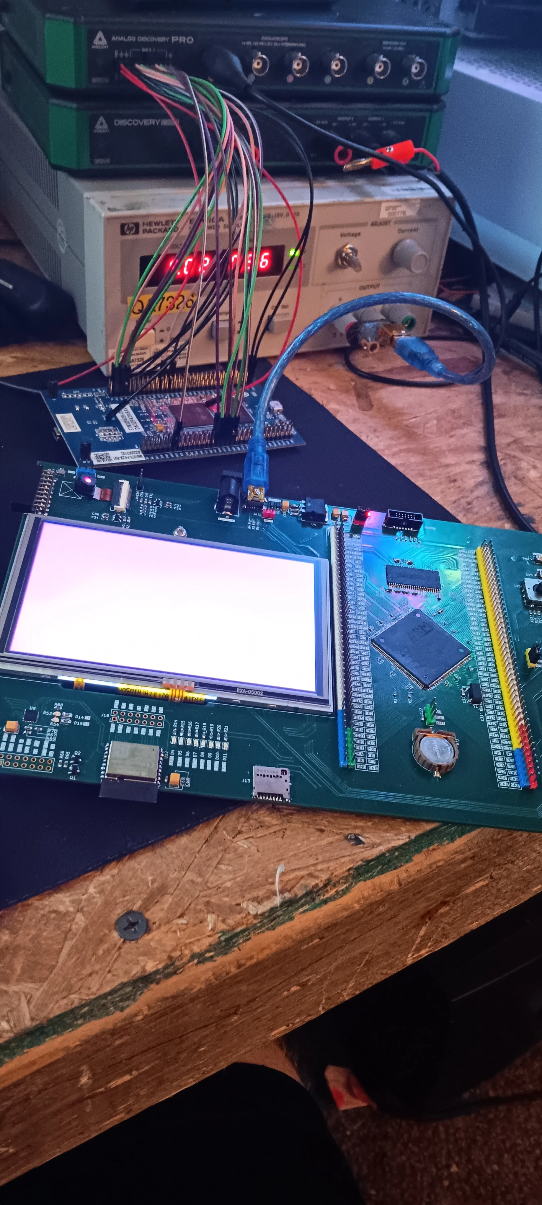
having trouble with the background displaying center on the adafruit 5 inch LCD CH500WV05A-T wondering if anyone has used this lcd with stm32f4 and have the HSW HBP HFP VSW VBP VFP values you used im guessing this is the issue ive used the ones from the datasheet and tried combinations of these values but nothing seems to work ill attach a picture of the screen trying to display a red background thanks for your time BTW the values ive used are LCD_HSW = 2LCD_HBP = 46LCD_HFP = 16LCD_VSW = 2LCD_VBP = 23LCD_VFP = 22
Hi there,I would like to control WS2812B LEDs with a PWM timer and DMA.There are various tutorials on this, but they have not helped me and I am now asking you. Because it requires slightly different configurations depending on the model (F3, F4, G4, G0), I'm a bit overwhelmed.I start a DMA transfer, wait for the last pulse with an interrupt and stop the DMA transfer. So far so good in theory. I still have problems with the implementation.Even the simplest DMA example without WS2812B protocol does not work for me.Clock SYSCLK/HCLK: 170 MHzTIM1 CH4 configuredPrescaler: 170-1 => 1 MHZCounter Preiod: 100-1 => 10 kHzDMAMemory -> PeripheralData Width: Word (32 bit)6 PWM pulses (= 600 us) should be sent outTIM1 Mode + ConfigurationDMA SettingsSource:TIM_HandleTypeDef htim1; DMA_HandleTypeDef hdma_tim1_ch4; /* never used?! */ uint32_t data[] = { 30, 80, 20, 60, 10, 50 }; void HAL_TIM_PWM_PulseFinishedCallback(TIM_HandleTypeDef *htim) { HAL_TIM_PWM_Stop_DMA(&htim1,
I was trying to build a flight controller with this board. I was using rizacelik's repo for this project. At first, i was using the 3.0.1 firmware .hex file but then later wanted to switch to the newer 8.0.0 firmware so i flashed the newer .hex file (e.g , inav_8.0.0_STM32F411CE.hex) because the MPU6050 module wired correctly would hang my board for some odd reason. after the flash it didn't necessarily hang the board, but didn't get proper reads yet. the gyro was detected, but not the accelerometer. I was tweaking all in the configuration tab and maybe the uart1 and usb in ports tab (i don't remember clearly what was my last action in the Inav program), then suddenly the board stopped working. i disconnected everything and came to see that the USB Type-C direct connection with my pc was not working anymore. i tried multiple other working cables, no clue. Then I used my ST-Link V2 programmer, and it connected the board. I used the Cube programmer to erase the chip memory and refla
I used Cude IDE version 1.18.1. successfully then upgraded and wrote the second project (timer). I'm using Nucelo-64 STM32 F411RE with clock rate 84Mhz. My new project is to use the TIM4 with the settings: PSC: 8399, CP: 10000 to toggle the LED per second. The LED doesn't turn on/off whatsoever. (My prior project - to use the user button - doesn't work either!)My files: lib.hpp: #ifndef INC_LIB_HPP_ #define INC_LIB_HPP #if __cplusplus extern "C" { #endif void run(); void HAL_GPIO_EXTI_Callback(uint16_t); void HAL_TIM_PeriodElapsedCallback(TIM_HandleTypeDef *); #if __cplusplus } #endif #endiflib.cpp:#include "main.h" #include "lib.hpp" #include <stdio.h> auto pressed = 0u; auto flag = false; void HAL_GPIO_EXTI_Callback(uint16_t GPIO_Pin) { if(GPIO_Pin == B1_Pin) flag = true; else flag = false; } void HAL_TIM_PeriodElapsedCallback(TIM_HandleTypeDef *htim) { HAL_GPIO_TogglePin(LED_GPIO_Port,LED_Pin); } void run() { while (1) { if(flag){ pres
Hi,I am using the ST link V2 debugger and i have updated the firmware using stm32 programmer software and used the stsw-link009 and when i tried connecting it shows me some below errors. After updating the firmware it worked for few moments and then it suddenly stopped. Thank YouDeekshitha.
I've been previously programming the STM32F103C6T6 blue pill with an FTDI via UART and am now trying to flash a USB bootloader binary to program it directly via USB.I've closely followed the guide on https://www.electrosoftcloud.com/en/stm32f103-bootloader-and-programming/ - I've successfully flashed the generic_bootloader_pc_13.bin file via UART, installed the required drivers, and followed the BOOT0 pattern correctly. On connecting via USB, the board is detected as "Maple DFU" in the Device Manager.But STM32CubeProgrammer keeps showing "No DFU detected" when I try connecting via USB and pressing the refresh button.However, when I enter the PID and VID specified in the Maple DFU driver properties shown below in STM32CubeProgrammer: On refreshing and trying to connect, the error "unknown or unsupported device" is displayed:I've followed several online resources, and nobody seems to encounter this issue.Can anyone provide any insights into why this might occur?
I am working with a custom board I designed using this display(LINK) They provide init codes on the product page that I have integrated into my project but they do not provide any any porch, timing or polarity information. I first setup LTDC and the DSI host and was able to display a solid color on the display by generating a frame buffer in code and setting each pixel. I then moved on to integrating touchGFX and was also able to get that working fairly easily but the display is mirrored on the x-axis as shown here:The display is using a ST7701s controller, I found the MADCTL register in the datasheet that I believe should be able to mirror the display but I am not getting the expected output. Here is how I am writing to this register HAL_DSI_ShortWrite(&hdsi, 0, DSI_DCS_SHORT_PKT_WRITE_P1, 0x36, 0x10); And this is the output after doing so I have verified the ability to write to this register by setting the "BGR" bit to a 1 and the display
I’m using NUCLEO STM32H753ZI.I use ST ID: STM32cudeIDEI have HardFault_Handler when call vTaskStart_Scheduler() using FreeRTOS Could you please let me know how to resolve this issue? Below is the sample code int main(void) { (void) HAL_Init(); /* Configure the system clock */ SystemClock_Config(); /* Enable the CPU Cache */ CPU_CACHE_Enable(); BaseType_t xReturned; TaskHandle_t xHandle = NULL; /* Create tasks / xReturned = xTaskCreate( Task_Code, “SB”, configMINIMAL_STACK_SIZE, (void) NULL, tskIDLE_PRIORITY+2U, &xHandle ); if( xReturned == pdPASS ) { vTaskStartScheduler(); } else { } while(1);
For a project i want to save log files in the external SPI of the Stm32n6 for this is already tried to configure xspi2 and the external memory, but i am not sure if i have done it right. I also have found no source on how to continue with the Code after this maybe someone can help with this.
I am using one of the 32 bit timers to measure intervals for fault protection on a HV pulse modulator. I have an interrupt on EXTI that captures both leading and trailing edges of the command pulse. In the service routine, I simply store the latest uptime and downtime to calc the pulsewidth and period....pretty simple. The pulsewidth is pretty small, so I use the free-running SYSTICK (400 MHz) for pulsewidth, but it is only 24 bits, so I need to use a 32 bit timer for the pulse period, and do so at 50 MHz.I initially coded this with TIM2, and it worked perfectly. Then I realized that I needed to use TIM2 elsewhere because I already wired a different time-critical signal to the TIM2.ETR pin (the ETR interrupt latency is far less than the EXTI latency). So I switched my code to use TIM5 for the period. This did not work. It bounces around semi-randomly, and by appearances is acting like a 16 bit timer.I switched to T
I use stm32 touch gfx tool ``TouchGFX 4.25.0 Designer`` generate a simple demo based on STM32H7B3I_EVAL board.but when I build this project on MDK542a, I get failed as below```STM32H7B3I_EVAL\STM32H7B3I_EVAL.axf: Error: L6406E: No space in execution regions with .ANY selector matching touchgfxgeneratedhal.o(.bss.TouchGFX_Framebuffer).STM32H7B3I_EVAL\STM32H7B3I_EVAL.axf: Error: L6406E: No space in execution regions with .ANY selector matching heap_4.o(.bss.ucHeap).STM32H7B3I_EVAL\STM32H7B3I_EVAL.axf: Error: L6406E: No space in execution regions with .ANY selector matching hardwaremjpegdecoder.o(TouchGFX_MCU_Data_OutBuffer0).STM32H7B3I_EVAL\STM32H7B3I_EVAL.axf: Error: L6406E: No space in execution regions with .ANY selector matching hardwaremjpegdecoder.o(TouchGFX_MCU_Data_OutBuffer1).STM32H7B3I_EVAL\STM32H7B3I_EVAL.axf: Error: L6406E: No space in execution regions with .ANY selector matching touchgfxconfiguration.o(.bss._ZZN12FrontendHeap11getInstanceEvE8instance).STM32H7B3I_
I successfully configured the I2S2 interface to a sample rate of 48KHz. The attached WCMCU-5102 is connected to these three wires. I2S2_WS = PA3I2S2_CK = PA5I2S2_SDO = PB1 FLT = GNDDMP = GNDSCL = GNDFMT = GND XMT = Vdd (3.3V) static void MX_I2S2_Init(void) { /* USER CODE BEGIN I2S2_Init 0 */ /* USER CODE END I2S2_Init 0 */ /* USER CODE BEGIN I2S2_Init 1 */ /* USER CODE END I2S2_Init 1 */ hi2s2.Instance = SPI2; hi2s2.Init.Mode = I2S_MODE_MASTER_TX; hi2s2.Init.Standard = I2S_STANDARD_PHILIPS; hi2s2.Init.DataFormat = I2S_DATAFORMAT_16B; hi2s2.Init.MCLKOutput = I2S_MCLKOUTPUT_DISABLE; hi2s2.Init.AudioFreq = I2S_AUDIOFREQ_48K; hi2s2.Init.CPOL = I2S_CPOL_LOW; hi2s2.Init.FirstBit = I2S_FIRSTBIT_MSB; hi2s2.Init.WSInversion = I2S_WS_INVERSION_DISABLE; hi2s2.Init.Data24BitAlignment = I2S_DATA_24BIT_ALIGNMENT_RIGHT; hi2s2.Init.MasterKeepIOState = I2S_MASTER_KEEP_IO_STATE_DISABLE; if (HAL_I2S_Init(&hi2s2) != HAL_OK) { Error_Handler(); } /* USER CODE BEGIN I2
ST Community highlights – April to June 2026
Already have an account? Login
No account yet? Create an account
Enter your E-mail address. We'll send you an e-mail with instructions to reset your password.