

RK.16
Associate
May 2, 2023
Solved

Why there are no signals on MOSI and SCK of SPI2 in my stm32f030c8?

  • May 2, 2023
  • 4 replies
  • 2267 views

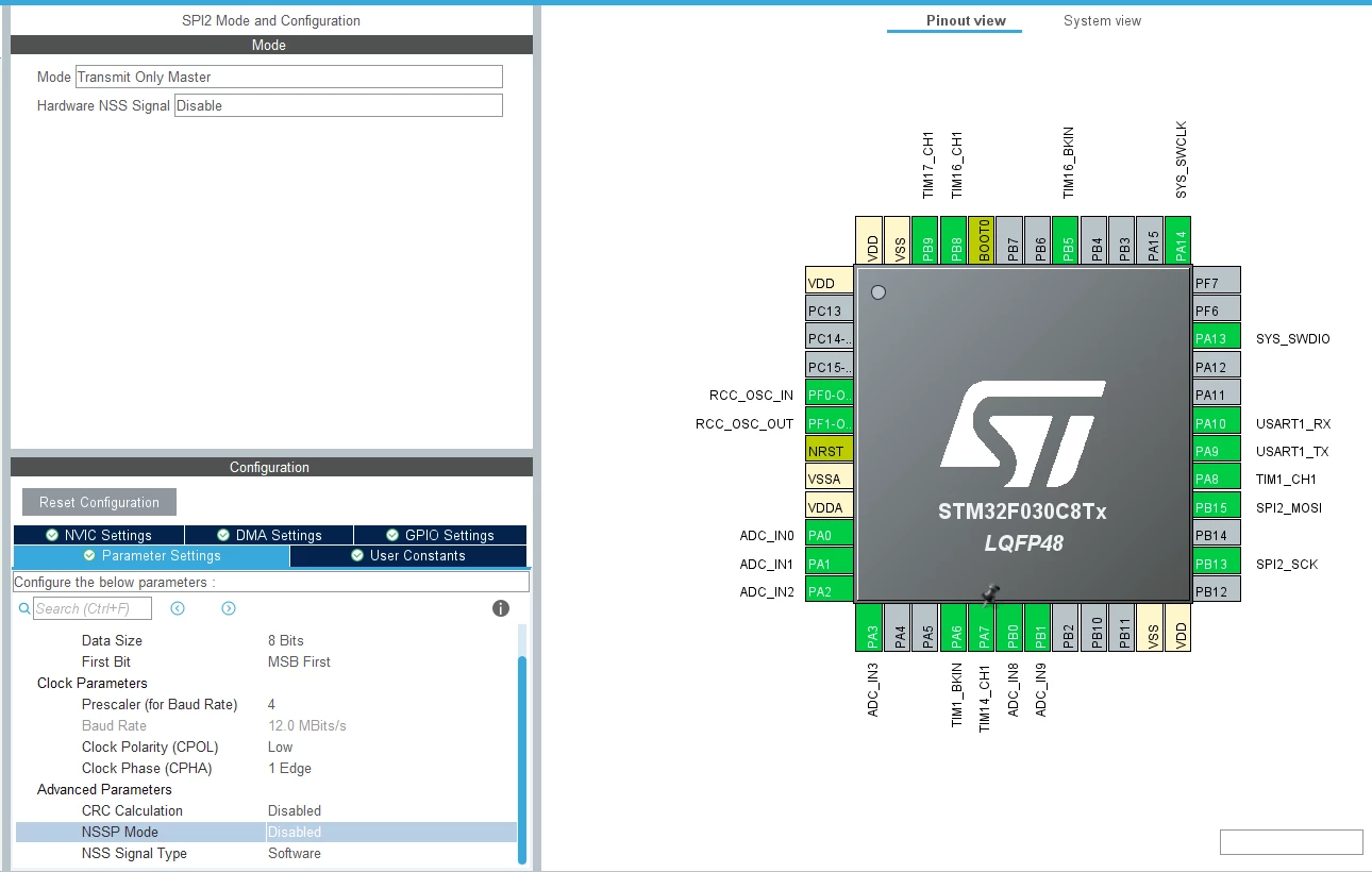
I am trying to connect LCD (SPI interface) to my custom stm32f030c8 board, PB13 -> SCK, PB15 -> MOSI (Transmitt only mode).

I created a test project with cube configurator (attached a screenshot).

I did not change anything in the generated code, just added sending test:

/* Initialize all configured peripherals */
 MX_GPIO_Init();
 MX_ADC_Init();
 MX_SPI2_Init();
 MX_TIM1_Init();
 MX_TIM14_Init();
 MX_TIM16_Init();
 MX_TIM17_Init();
 MX_USART1_UART_Init();
 /* USER CODE BEGIN 2 */
 
 uint8_t testData[] = { 0x11, 0x22, 0x33, 0x44 };
 HAL_SPI_Transmit(&hspi2, testData, 4, 5000);
 /* USER CODE END 2 */
 
 /* Infinite loop */
 /* USER CODE BEGIN WHILE */
 while (1)
 {
 /* USER CODE END WHILE */
 
 /* USER CODE BEGIN 3 */
 }

I uses ST-Link to debug. All initializations pass so as the transmit subroutine, but there are no any signals on MOSI and SCK appears (I use oscilloscope with sync by signal front). I tried to change pins mode to general outputs and to toggle output levels manualy, and I got that levels on my oscilloscope, so there are no broken lines.

In SR register only TXE is set, in CR1 register SPE is set, all seems to fine.

So why there are no SPI signals?

I checked GPIOs config, looks right:

/* Peripheral clock enable */
 __HAL_RCC_SPI2_CLK_ENABLE();
 
 __HAL_RCC_GPIOB_CLK_ENABLE();
 /**SPI2 GPIO Configuration
 PB13 ------> SPI2_SCK
 PB15 ------> SPI2_MOSI
 */
 GPIO_InitStruct.Pin = GPIO_PIN_13|GPIO_PIN_15;
 GPIO_InitStruct.Mode = GPIO_MODE_AF_PP;
 GPIO_InitStruct.Pull = GPIO_NOPULL;
 GPIO_InitStruct.Speed = GPIO_SPEED_FREQ_HIGH;
 GPIO_InitStruct.Alternate = GPIO_AF0_SPI2;
 HAL_GPIO_Init(GPIOB, &GPIO_InitStruct);


_legacyfs_online_stmicro_images_0693W00000bjBjeQAE.png

This topic has been closed for replies.
Best answer by Peter BENSCH

Welcome, @Community member​, to the community!

You call HAL_SPI_Transmit exactly once after the start. Since you are only transmitting 4 bytes, i.e. 32 bits with 12MHz, it takes approx. 2.7µs after the reset. Are you sure that you will be able to capture this after the reset?

Maybe you put the transmit in the while loop?

Regards

/Peter

4 replies

Peter BENSCH
Peter BENSCHBest answer
ST Technical Moderator
May 2, 2023

Welcome, @Community member​, to the community!

You call HAL_SPI_Transmit exactly once after the start. Since you are only transmitting 4 bytes, i.e. 32 bits with 12MHz, it takes approx. 2.7µs after the reset. Are you sure that you will be able to capture this after the reset?

Maybe you put the transmit in the while loop?

Regards

/Peter

In order to give better visibility on the answered topics, please click on Accept as Solution on the reply which solved your issue or answered your question.
RK.16
RK.16Author
Associate
May 2, 2023

I set breakpoint at transmit call, and repeat it with "move to line".

But I think it's a good idea to see (or not to see) infinite number of pulses at SCK, I'll try it right now.

Peter BENSCH
ST Technical Moderator
May 2, 2023

This is a false assumption. SPI works similar to a shift register: the clock at SCK occurs exactly during the data to be transmitted, so it is only visible for that long, in your case for 4*8 = 32 bits.

In order to give better visibility on the answered topics, please click on Accept as Solution on the reply which solved your issue or answered your question.
RK.16
RK.16Author
Associate
May 2, 2023

I'm sorry, signals are where they should be, my mistake that frequency was too high, and osc's trigger just skipped short pulses. Solution was setting higher prescaler to SPI2 and put transmition into a loop while. Thank you for your responses.