Turn on suggestions
Auto-suggest helps you quickly narrow down your search results by suggesting possible matches as you type.
Showing results for
- STMicroelectronics Community
- STM32 MCUs
- STM32 MCUs Products
- STM32F446 DAC DMA with asymmetrical output
Options
- Subscribe to RSS Feed
- Mark Topic as New
- Mark Topic as Read
- Float this Topic for Current User
- Bookmark
- Subscribe
- Mute
- Printer Friendly Page
STM32F446 DAC DMA with asymmetrical output
Options
- Mark as New
- Bookmark
- Subscribe
- Mute
- Subscribe to RSS Feed
- Permalink
- Email to a Friend
- Report Inappropriate Content
2024-06-16 1:26 PM - last edited on 2024-06-21 6:28 AM by Amel NASRI
Hi all,
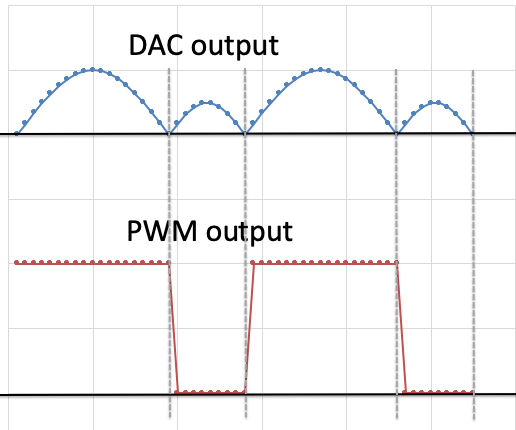
I need to generate a DAC output which is operating on 2 quadrants and the quadrants may be asymmetrical with respect to both the duty cycle and the amplitude. Attached a picture which better explains what I need.
MCU STM32F446RE
DAC OUT1 on pin PA4 - triggered by TIM6
DMA channel 1 stream 5
PWM out: TIM1 CH3 with output on pin PA10
frequency range: 10-500Hz (frequency of the DAC waveform)
The PWM output is controlling the polarity while the DAC is controlling the output amplitude. The polarity must be changed when the DAC output completes 1 cycle.
I need ideas on how to implement it. Since the DAC output is asymmetric I don't know how to create the LUT: should I create a complete LUT with both the quadrants or should I change the LUT array at the polarity change ?
In the first case I don't know how to trigger the PWM output in sync with the DAC waveform while, in the second case, I don't know if I have enough time to recalculate the LUT at the polarity change.
Another option I was thinking is to use a standard GPIO (on pin PA10) instead of the PWM, which I can toggle at the DAC zero crossing, but this will need to "ping-pong" between 2 different LUTs and I don't know how to do it.
Ay ideas on how to proceed ?
Thanks,
Max
Solved! Go to Solution.
Labels:
- Labels:
-
STM32F4 Series
1 ACCEPTED SOLUTION
Accepted Solutions
Options
- Mark as New
- Bookmark
- Subscribe
- Mute
- Subscribe to RSS Feed
- Permalink
- Email to a Friend
- Report Inappropriate Content
2024-06-17 4:10 AM
> should I create a complete LUT with both the quadrants
This.
Make TIM1 period an integer multiple of TIM6, set up DAC and up circular DMA to the precalculated values. Then, if you set the two timers up completely without starting them (setting TIMx_CR.CEN), globally disable interrupts, start both timers, reenable interrupts, lean back and enjoy the result.
The difference between the timers will be a few machine cycles which is problably negligible. You can compensate for whatever timing difference by setting one of the timers' CNT to nonzero before enabling.
You can go full fancy with using different-than-TIM6 for DAC triggering, and start the two timers in strict sync by triggering one from the other through their TRGI-TRGO link, but in the vast majority of practical cases the timing difference/jitter resulting from the simple and easy way is negligible.
JW
7 REPLIES 7
Options
- Mark as New
- Bookmark
- Subscribe
- Mute
- Subscribe to RSS Feed
- Permalink
- Email to a Friend
- Report Inappropriate Content
2024-06-17 4:10 AM
> should I create a complete LUT with both the quadrants
This.
Make TIM1 period an integer multiple of TIM6, set up DAC and up circular DMA to the precalculated values. Then, if you set the two timers up completely without starting them (setting TIMx_CR.CEN), globally disable interrupts, start both timers, reenable interrupts, lean back and enjoy the result.
The difference between the timers will be a few machine cycles which is problably negligible. You can compensate for whatever timing difference by setting one of the timers' CNT to nonzero before enabling.
You can go full fancy with using different-than-TIM6 for DAC triggering, and start the two timers in strict sync by triggering one from the other through their TRGI-TRGO link, but in the vast majority of practical cases the timing difference/jitter resulting from the simple and easy way is negligible.
JW
Options
- Mark as New
- Bookmark
- Subscribe
- Mute
- Subscribe to RSS Feed
- Permalink
- Email to a Friend
- Report Inappropriate Content
2024-06-17 11:19 PM - edited 2024-06-17 11:42 PM
Thanks Jan, I like the idea of the master/slave timer. TIM2 was used to trigger the ADC for other purposes so I changed the architecture and now I'm using TIM2 (as slave) for the DAC, triggered by TIM1 (as master) that I'm still using the generate the polarity PWM signal. After I determined the prescaler value for TIM1, I'm using a prescaler value for TIM2 which is TIM1_PSC/#_of_LUT_points; by doing this I can load the same value for ARR on both the timers and I should always end up with synchronized periods. Also the calculation of the CCR for TIM1_PWM is easier as it will follow exactly the LUT points.
I'll test the solution later today or tomorrow and let you know if it works.
Thanks for your help!
Max
Options
- Mark as New
- Bookmark
- Subscribe
- Mute
- Subscribe to RSS Feed
- Permalink
- Email to a Friend
- Report Inappropriate Content
2024-06-19 9:37 AM - edited 2024-06-19 9:43 AM
and it works!
TIM1 is used as master with PWM output and TIM2 is used as slave to trigger the DAC. I had some issues at the beginning because I realize later on that TIM1 is attached to APB2 with double the clock with respect to TIM2 which is attached to APB1! I've then set APB2 with the same clock and TIM2_PSC = TIM1_PSC/#_LUT_points: by doing this I-m using the same value for ARR on both the timers and I'm good to go.
The frequency is adjustable from 10 to 500Hz and duty cycle from 20 to 95 %
Here attached an example at 200Hz with 60% DC.
Many thanks Jan for your great help!
Ciao,
Max
Options
- Mark as New
- Bookmark
- Subscribe
- Mute
- Subscribe to RSS Feed
- Permalink
- Email to a Friend
- Report Inappropriate Content
2024-06-21 2:30 AM - edited 2024-06-21 2:36 AM
Hello again,
I noticed that, despite the 2 timers are synchronized, there is a delay of TIM2 (slave) with respect to TIM1 (master). Please have a look at the attached picture to better understand the issue.
I think we have 2 problems here:
- TIM2 is not perfectly synchronized with TIM1 - the minimum delay that I measure is around 36usec. This is acceptable for my application but I was expecting a better sync considering that the core is running at 180Mhz...
- The first point of the DMA LUT is delayed by about 85usec, and this is still acceptable but we are at the limit. Maybe here I'm messing up with something in the code and I'm asking your help in understand what this could be
I've tried to play with the master/slave mode option on both the timers (the one that is referring to delay the TRGO/TRGI) but nothing is changing in the waveforms. Also, it is not clear to me if this option needs to be enabled on the Master or on the Slave timer....
Overall I'm ok with the solution I've implemented but I want to understand if I do something wrong and how I can improve.
Thanks,
Max

the following picture is showing the delay between the polarity PWM period start (TIM1 - master) vs the DAC LUT period start (triggered by TIM2). TIM2_PWM has been activated only for measuring purposes.

this is showing the minimum delay between TIM1_PWM (master) and TIM2_PWM(slave)

Options
- Mark as New
- Bookmark
- Subscribe
- Mute
- Subscribe to RSS Feed
- Permalink
- Email to a Friend
- Report Inappropriate Content
2024-06-22 1:42 AM
I don't know how exactly do you perform the synchronization and DMA start. Details do matter.
Generally, if you use Trigger mode of the slave-mode controller to perform synchronization, the slave timer must not be enabled by software (i.e. TIM2_CR1.CEN must remain 0 until the master is run).
JW
Options
- Mark as New
- Bookmark
- Subscribe
- Mute
- Subscribe to RSS Feed
- Permalink
- Email to a Friend
- Report Inappropriate Content
2024-06-22 2:35 AM
Here the init of the involved Timers + the 3 instructions used to start everything. The PWM start for TIM2 is used only for debug purposes so I can see PMW signal and measure the difference.
It is maybe that I have to start the DAC DMA after the master timer ?
static void MX_TIM1_Init(void)
{

  /* USER CODE BEGIN TIM1_Init 0 */

  /* USER CODE END TIM1_Init 0 */

  TIM_ClockConfigTypeDef sClockSourceConfig = {0};
  TIM_MasterConfigTypeDef sMasterConfig = {0};
  TIM_OC_InitTypeDef sConfigOC = {0};
  TIM_BreakDeadTimeConfigTypeDef sBreakDeadTimeConfig = {0};

  /* USER CODE BEGIN TIM1_Init 1 */

  /* USER CODE END TIM1_Init 1 */
  htim1.Instance = TIM1;
  htim1.Init.Prescaler = 399;
  htim1.Init.CounterMode = TIM_COUNTERMODE_UP;
  htim1.Init.Period = 450;
  htim1.Init.ClockDivision = TIM_CLOCKDIVISION_DIV1;
  htim1.Init.RepetitionCounter = 0;
  htim1.Init.AutoReloadPreload = TIM_AUTORELOAD_PRELOAD_DISABLE;
  if (HAL_TIM_Base_Init(&htim1) != HAL_OK)
  {
    Error_Handler();
  }
  sClockSourceConfig.ClockSource = TIM_CLOCKSOURCE_INTERNAL;
  if (HAL_TIM_ConfigClockSource(&htim1, &sClockSourceConfig) != HAL_OK)
  {
    Error_Handler();
  }
  if (HAL_TIM_PWM_Init(&htim1) != HAL_OK)
  {
    Error_Handler();
  }
  sMasterConfig.MasterOutputTrigger = TIM_TRGO_UPDATE;
  sMasterConfig.MasterSlaveMode = TIM_MASTERSLAVEMODE_DISABLE;
  if (HAL_TIMEx_MasterConfigSynchronization(&htim1, &sMasterConfig) != HAL_OK)
  {
    Error_Handler();
  }
  sConfigOC.OCMode = TIM_OCMODE_PWM1;
  sConfigOC.Pulse = 225;
  sConfigOC.OCPolarity = TIM_OCPOLARITY_HIGH;
  sConfigOC.OCNPolarity = TIM_OCNPOLARITY_HIGH;
  sConfigOC.OCFastMode = TIM_OCFAST_DISABLE;
  sConfigOC.OCIdleState = TIM_OCIDLESTATE_RESET;
  sConfigOC.OCNIdleState = TIM_OCNIDLESTATE_RESET;
  if (HAL_TIM_PWM_ConfigChannel(&htim1, &sConfigOC, TIM_CHANNEL_3) != HAL_OK)
  {
    Error_Handler();
  }
  sBreakDeadTimeConfig.OffStateRunMode = TIM_OSSR_DISABLE;
  sBreakDeadTimeConfig.OffStateIDLEMode = TIM_OSSI_DISABLE;
  sBreakDeadTimeConfig.LockLevel = TIM_LOCKLEVEL_OFF;
  sBreakDeadTimeConfig.DeadTime = 0;
  sBreakDeadTimeConfig.BreakState = TIM_BREAK_DISABLE;
  sBreakDeadTimeConfig.BreakPolarity = TIM_BREAKPOLARITY_HIGH;
  sBreakDeadTimeConfig.AutomaticOutput = TIM_AUTOMATICOUTPUT_DISABLE;
  if (HAL_TIMEx_ConfigBreakDeadTime(&htim1, &sBreakDeadTimeConfig) != HAL_OK)
  {
    Error_Handler();
  }
  /* USER CODE BEGIN TIM1_Init 2 */

  /* USER CODE END TIM1_Init 2 */
  HAL_TIM_MspPostInit(&htim1);

}

static void MX_TIM2_Init(void)
{

  /* USER CODE BEGIN TIM2_Init 0 */

  /* USER CODE END TIM2_Init 0 */

  TIM_ClockConfigTypeDef sClockSourceConfig = {0};
  TIM_SlaveConfigTypeDef sSlaveConfig = {0};
  TIM_MasterConfigTypeDef sMasterConfig = {0};
  TIM_OC_InitTypeDef sConfigOC = {0};

  /* USER CODE BEGIN TIM2_Init 1 */

  /* USER CODE END TIM2_Init 1 */
  htim2.Instance = TIM2;
  htim2.Init.Prescaler = 1;
  htim2.Init.CounterMode = TIM_COUNTERMODE_UP;
  htim2.Init.Period = 450;
  htim2.Init.ClockDivision = TIM_CLOCKDIVISION_DIV1;
  htim2.Init.AutoReloadPreload = TIM_AUTORELOAD_PRELOAD_DISABLE;
  if (HAL_TIM_Base_Init(&htim2) != HAL_OK)
  {
    Error_Handler();
  }
  sClockSourceConfig.ClockSource = TIM_CLOCKSOURCE_INTERNAL;
  if (HAL_TIM_ConfigClockSource(&htim2, &sClockSourceConfig) != HAL_OK)
  {
    Error_Handler();
  }
  if (HAL_TIM_PWM_Init(&htim2) != HAL_OK)
  {
    Error_Handler();
  }
  sSlaveConfig.SlaveMode = TIM_SLAVEMODE_TRIGGER;
  sSlaveConfig.InputTrigger = TIM_TS_ITR0;
  if (HAL_TIM_SlaveConfigSynchro(&htim2, &sSlaveConfig) != HAL_OK)
  {
    Error_Handler();
  }
  sMasterConfig.MasterOutputTrigger = TIM_TRGO_UPDATE;
  sMasterConfig.MasterSlaveMode = TIM_MASTERSLAVEMODE_ENABLE;
  if (HAL_TIMEx_MasterConfigSynchronization(&htim2, &sMasterConfig) != HAL_OK)
  {
    Error_Handler();
  }
  sConfigOC.OCMode = TIM_OCMODE_PWM1;
  sConfigOC.Pulse = 200;
  sConfigOC.OCPolarity = TIM_OCPOLARITY_HIGH;
  sConfigOC.OCFastMode = TIM_OCFAST_DISABLE;
  if (HAL_TIM_PWM_ConfigChannel(&htim2, &sConfigOC, TIM_CHANNEL_2) != HAL_OK)
  {
    Error_Handler();
  }
  /* USER CODE BEGIN TIM2_Init 2 */

  /* USER CODE END TIM2_Init 2 */
  HAL_TIM_MspPostInit(&htim2);

}

....
HAL_DAC_Start_DMA(&hdac, DAC_CHANNEL_1, (uint32_t*)DAC_wave, 200, DAC_ALIGN_12B_R);
HAL_TIM_PWM_Start(&htim1,TIM_CHANNEL_3);
HAL_TIM_PWM_Start(&htim2,TIM_CHANNEL_2);     //DEBUG
....
Options
- Mark as New
- Bookmark
- Subscribe
- Mute
- Subscribe to RSS Feed
- Permalink
- Email to a Friend
- Report Inappropriate Content
2024-06-22 9:16 AM
I don't use Cube.
And details do matter. You need to dig into Cube (it's open source) to find out those details, in conjunction with the Reference Manual.
JW
Related Content
- Demo STM32 -> PC via FT232H/2232H async. Parallel - throughput >7.5MByte/s. in Others: STM32 MCUs related
- ADDR10 flag is set when sending 7 bit address in STM32 MCUs Products
- STM32F446 SPI SLAVE IN DMA RECEIVES DATA BUT DOES NOT TRANSMIT in STM32 MCUs Products
- How to enable Complementary Output and Normal Output with Output Compare in TIM in STM32 MCUs Products