Turn on suggestions
Auto-suggest helps you quickly narrow down your search results by suggesting possible matches as you type.
Showing results for
- STMicroelectronics Community
- Product forums
- Power management
- Re: Potential datasheet error - STEVAL-GMBL / STEV...
Options
- Subscribe to RSS Feed
- Mark Topic as New
- Mark Topic as Read
- Float this Topic for Current User
- Bookmark
- Subscribe
- Mute
- Printer Friendly Page
Potential datasheet error - STEVAL-GMBL / STEVAL-UKI001V1 / UM2460 / DB3710
Options
- Mark as New
- Bookmark
- Subscribe
- Mute
- Subscribe to RSS Feed
- Permalink
- Email to a Friend
- Report Inappropriate Content
2022-04-21 09:19 AM
Hi guys, i just spent a few hours fiddling with the STEVAL-GMBL and adapter board, and i think i found an error in the datasheet. Not sure if should post here or just open a ticket.
Page 5 of the file DB3710, as well as pages 6,7,26 of file DB3710 show the "STEVAL-UKI001V1 adapter board schematic diagram", the relevant part is the "10 to 20 pin Serial Wire Debug (SWD) adapter". The diagram doesn't show the notch of the header, just "J1" as information. Either the J1 is misplaced here, or on the "STEVAL-UKI001V1" board, as they are in opposite corners of the connector. In the datasheet, J1 is in the top left next to pin 1, VDD_TARGET, on the board it is printed on the bottom right, pin 20, GND.
Since there is no notch to properly differentiate the rotation, readers will definitively use wrong pins.
Solved! Go to Solution.
Labels:
- Labels:
-
Motor Control Hardware
1 ACCEPTED SOLUTION
Accepted Solutions
Options
- Mark as New
- Bookmark
- Subscribe
- Mute
- Subscribe to RSS Feed
- Permalink
- Email to a Friend
- Report Inappropriate Content
2022-04-29 06:35 AM
Hello
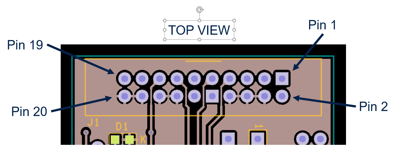
Normally the name of the symbol (in this case the J1) is not used to indicate information about the component orientation. So we can't consider the placement of the J1 serigraphy a mismatch error.
And normally the notch of the header is always in the side of the pin 1 of the connector.
So, please consider the attached image as reference.
Ciao
Gigi
1 REPLY 1
Options
- Mark as New
- Bookmark
- Subscribe
- Mute
- Subscribe to RSS Feed
- Permalink
- Email to a Friend
- Report Inappropriate Content
2022-04-29 06:35 AM
Hello
Normally the name of the symbol (in this case the J1) is not used to indicate information about the component orientation. So we can't consider the placement of the J1 serigraphy a mismatch error.
And normally the notch of the header is always in the side of the pin 1 of the connector.
So, please consider the attached image as reference.
Ciao
Gigi
Related Content
- H5 ADC clock in STM32CubeIDE (MCUs)
- STM32H747I-DISCO, codec outputs noise in BSP example. in STM32 MCUs Embedded software
- Using OCXO as an External Oscillator for STM32H533 in STM32 MCUs Products
- ST25R3916 Max Allowed Voltage Level on RFI in ST25 NFC/RFID tags and readers
- TouchGFX Frame Buffer: image inverted at corners in STM32 MCUs TouchGFX and GUI