Turn on suggestions
Auto-suggest helps you quickly narrow down your search results by suggesting possible matches as you type.
Showing results for
- STMicroelectronics Community
- Product forums
- Power management
- Re: How can we increase soft start time for VIPER3...
Options
- Subscribe to RSS Feed
- Mark Topic as New
- Mark Topic as Read
- Float this Topic for Current User
- Bookmark
- Subscribe
- Mute
- Printer Friendly Page
How can we increase soft start time for VIPER319XDTR?
Options
- Mark as New
- Bookmark
- Subscribe
- Mute
- Subscribe to RSS Feed
- Permalink
- Email to a Friend
- Report Inappropriate Content
2021-06-21 01:34 AM
Dear sir,
We have followed STEVAL-VP319X1B development board schematic for converting 110V/230V AC to 5V DC. In one of board we found that inrush current limiting resistor is burn out. We have followed same part number for resistor which is in development kit BOM. Can you suggest how we can increase soft start time.
Thanks
Kadam
Solved! Go to Solution.
1 ACCEPTED SOLUTION
Accepted Solutions
Options
- Mark as New
- Bookmark
- Subscribe
- Mute
- Subscribe to RSS Feed
- Permalink
- Email to a Friend
- Report Inappropriate Content
2021-08-10 06:59 AM
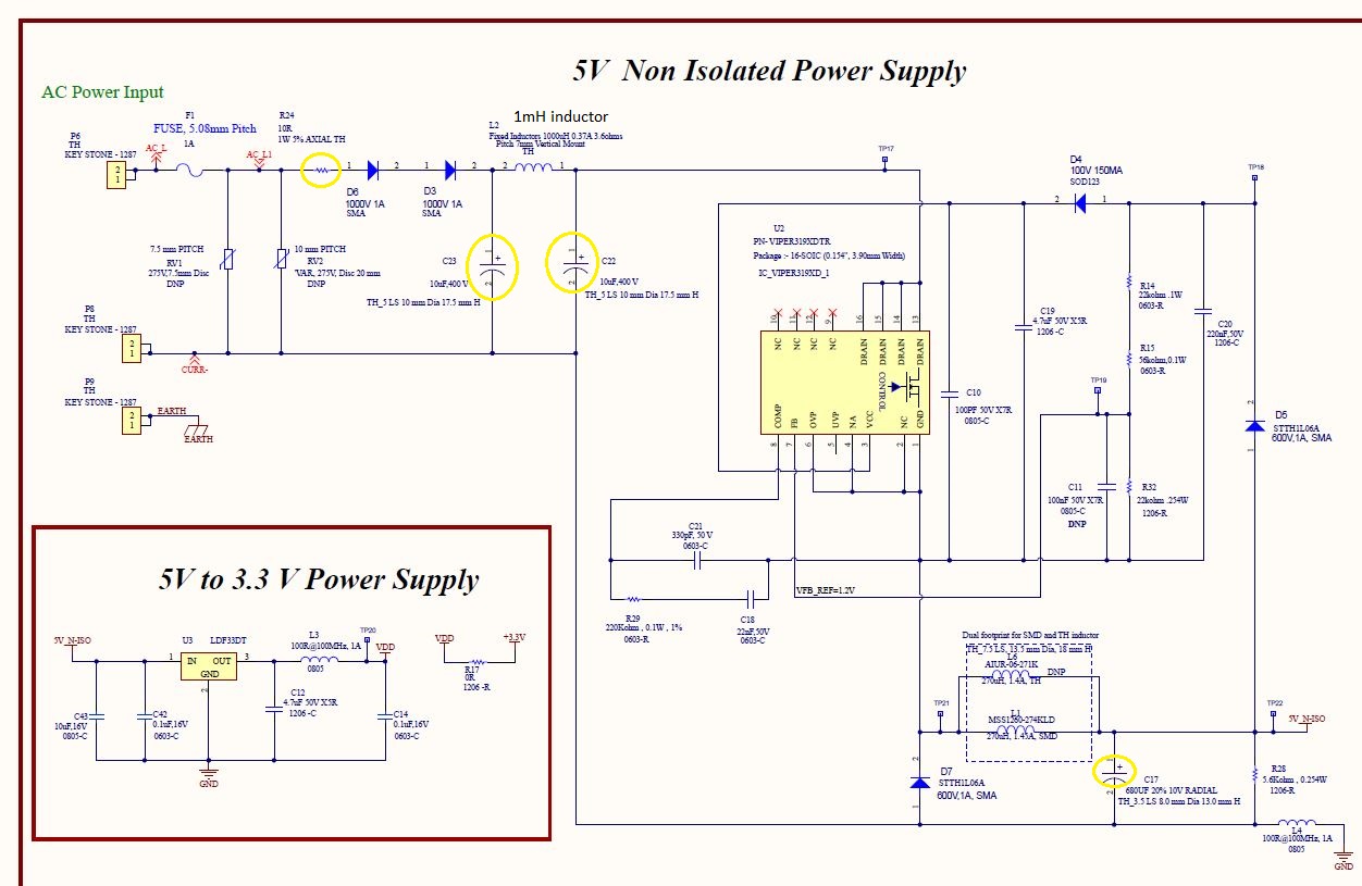
OK, now the schematic is visible.
C22, L2 and C23 form a low-pass filter to remove high frequency switching signals that would otherwise have an impact on the network. Instead of removing the capacitors or reducing their values, it may be better to use a PTC instead of R24.
Regards
/Peter
In order to give better visibility on the answered topics, please click on Accept as Solution on the reply which solved your issue or answered your question.
14 REPLIES 14
Options
- Mark as New
- Bookmark
- Subscribe
- Mute
- Subscribe to RSS Feed
- Permalink
- Email to a Friend
- Report Inappropriate Content
2021-06-21 02:38 AM
The soft start time of the VIPER31x is fixed to typically 8ms, as mentioned in its datasheet, table 7.
What about the parameters of the other components, like input filter capacitors and buck inductor (saturation current)?
Regards
/Peter
In order to give better visibility on the answered topics, please click on Accept as Solution on the reply which solved your issue or answered your question.
Options
- Mark as New
- Bookmark
- Subscribe
- Mute
- Subscribe to RSS Feed
- Permalink
- Email to a Friend
- Report Inappropriate Content
2021-06-21 03:10 AM

Options
- Mark as New
- Bookmark
- Subscribe
- Mute
- Subscribe to RSS Feed
- Permalink
- Email to a Friend
- Report Inappropriate Content
2021-07-11 09:32 AM
Dear sir,
We have followed same schematic as per development kit for Viper 319. We are facing issue for inrush current. In our prototype inrush current limit resistor is burn out due to higher inrush current. As we have simulate development kit schematic in Orcad Pspice. We found that pick inrush current is up to 20A. Please suggest how we can reduce inrush current?
Options
- Mark as New
- Bookmark
- Subscribe
- Mute
- Subscribe to RSS Feed
- Permalink
- Email to a Friend
- Report Inappropriate Content
2021-07-17 07:00 AM
Hi Peter Bensch,
In our proto, we sometimes get issue of burning resistor R1 during power ON-OFF and we are getting inrush current of 5A. Can you provide some suggestion for controlling input inrush current?
Thanks
Kadam
Options
- Mark as New
- Bookmark
- Subscribe
- Mute
- Subscribe to RSS Feed
- Permalink
- Email to a Friend
- Report Inappropriate Content
2021-07-19 06:58 AM
As mentioned before the VIPer319 limits the inrush current with the built-in soft start function, which is internally set to 8ms.
The large inrush current may therefore come from the two input capacitors. To be on the safe side, please check again whether you actually only have 10µF for both of them, as well as 1mH for L1?
Some possibilities to limit the inrush current:
- reduce C1
- increase L1
- substitute R1 by a e.g. PTC
Regards
/Peter
In order to give better visibility on the answered topics, please click on Accept as Solution on the reply which solved your issue or answered your question.
Options
- Mark as New
- Bookmark
- Subscribe
- Mute
- Subscribe to RSS Feed
- Permalink
- Email to a Friend
- Report Inappropriate Content
2021-08-09 10:16 PM
Hi Peter Bensch,
Below is snapshot of actual schematic.
If we keep R24 10E,1W we have observation that with AC input 230V,50Hz, sometimes R24 gets damaged.
When we replace R24 with 10E,3W. It works fine and observation is that inrush is still 2 to 6A.
Later on analysis we have found that Max inrush across R24 is observed around 2 to 6A with pulse time period of 5-6mS.
As preliminary solution we are planning to increase wattage of R24 to 5W.
Please share your view regarding this.
On the other end we planning to reduce input capacitance by non populating C23.
What is minimum recommended input capacitance value for faithful operation of VIPER319XDTR?
Thanks
Kadam
Options
- Mark as New
- Bookmark
- Subscribe
- Mute
- Subscribe to RSS Feed
- Permalink
- Email to a Friend
- Report Inappropriate Content
2021-08-10 01:55 AM
You forgot to insert the circuit diagram.
However, have you ever considered using a PTC instead of your current limiting resistor (R24)?
Regards
/Peter
In order to give better visibility on the answered topics, please click on Accept as Solution on the reply which solved your issue or answered your question.
Options
- Mark as New
- Bookmark
- Subscribe
- Mute
- Subscribe to RSS Feed
- Permalink
- Email to a Friend
- Report Inappropriate Content
2021-08-10 06:43 AM
Options
- Mark as New
- Bookmark
- Subscribe
- Mute
- Subscribe to RSS Feed
- Permalink
- Email to a Friend
- Report Inappropriate Content
2021-08-10 06:59 AM
OK, now the schematic is visible.
C22, L2 and C23 form a low-pass filter to remove high frequency switching signals that would otherwise have an impact on the network. Instead of removing the capacitors or reducing their values, it may be better to use a PTC instead of R24.
Regards
/Peter
In order to give better visibility on the answered topics, please click on Accept as Solution on the reply which solved your issue or answered your question.
Related Content
- DFU leave issue on STM32G0B1 in STM32 MCUs Products
- HSO firmware configuration in STM32 MCUs Motor control
- The relationship between the System Timer Module counter and the real time in Automotive MCUs
- STM32F415 DMA SPI transfer after stop mode in STM32 MCUs Products
- EEPROM Emulation works, but to program again I have to erase the entire flash. in STM32CubeIDE (MCUs)