Turn on suggestions
Auto-suggest helps you quickly narrow down your search results by suggesting possible matches as you type.
Showing results for
- STMicroelectronics Community
- MEMS and sensors
- MEMS (sensors)
- LSM6DSO SPI communication problem
Options
- Subscribe to RSS Feed
- Mark Topic as New
- Mark Topic as Read
- Float this Topic for Current User
- Bookmark
- Subscribe
- Mute
- Printer Friendly Page
LSM6DSO SPI communication problem
Options
- Mark as New
- Bookmark
- Subscribe
- Mute
- Subscribe to RSS Feed
- Permalink
- Email to a Friend
- Report Inappropriate Content
2019-01-24 02:17 AM
Good morning,
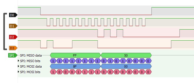
I am trying to read the WHO_AM_I register from LSM6DSO, but it doesn't respond as needed. I will attach a picture from signal analyzer (D0 is CS, D1 is CLK, D2 is MISO, D3 is MOSI). It looks like its respond is 0x50 instead of 0x6C. What should I change?
I tried with a MAX32630 and it was working (8 bits transfer mode).
When I try with RS14100 (16 bits mode) it responds with 0x50 instead of 6C.
Gabriel
Labels:
- Labels:
-
INEMO-Inertial Modules
13 REPLIES 13
Options
- Mark as New
- Bookmark
- Subscribe
- Mute
- Subscribe to RSS Feed
- Permalink
- Email to a Friend
- Report Inappropriate Content
2019-01-25 01:41 AM
Hi Eleon, as far as I can see, the problem occurs when I am connecting the same voltage on VDDIO as for VDD, but it shouldn't happen this, right? Now I am using 3.3V for VDD and 1.8V for IO and it looks like is working.
I don't know yet, but I get no answer from sensor if I set the 8bit on master. I raised a ticket to them as well.
Options
- Mark as New
- Bookmark
- Subscribe
- Mute
- Subscribe to RSS Feed
- Permalink
- Email to a Friend
- Report Inappropriate Content
2019-01-25 01:59 AM
hi Gabriel, consider that the best working region for these sensors is VDD=1.8V (and VDD_IO also 1.8V). Do you mean that you are facing issues if VDD=VDD_IO=1.8V and VDD=VDD_IO=3.3V, or only in 3.3V case? (VDD>= VDD_IO is anyway a good choice).
Btw in some rare cases 16bit definition includes in the frame length 8bit command + 8 bit data, but I don't now if it's the case of the RS14100.
Options
- Mark as New
- Bookmark
- Subscribe
- Mute
- Subscribe to RSS Feed
- Permalink
- Email to a Friend
- Report Inappropriate Content
2019-01-25 02:15 AM
I was trying with VDD=VDDIO=3.3V. I will try with both 1.8V in a bit.
Options
- Mark as New
- Bookmark
- Subscribe
- Mute
- Subscribe to RSS Feed
- Permalink
- Email to a Friend
- Report Inappropriate Content
2019-01-31 07:27 AM
btw, is the supply the same for both master RS14100 and slave LSM6DSO? My concern is that if you have different digital levels, the data can be misunderstood by both master and slave. The operating condition I read on RS14100 product brief are the following:
- Single supply: 2.1 to 3.6V or 1.85V
For a side check, could you try with the I2C interface (with pull-up resistors) instead of SPI?
http://www.redpinesignals.com/pdfs/RS14100_WiSeMCU_Product_Brief.pdf
- « Previous
-
- 1
- 2
- Next »