Associate II
January 27, 2025
Solved

I want to upload the led blinking code through the ftdi module.

  • January 27, 2025
  • 21 replies
  • 3081 views

Hi, I am using the STM32 NUCLEO-F401RE board and have already use the HAL APIs to blink the led. now I want to blink the onboard user led [LD2] using the FTDI module and want to use the USART6 for it can anyone please help and explain me in detail that how I will be doing this?

This topic has been closed for replies.
Best answer by mohite25


mohite25_0-1738649452294.png

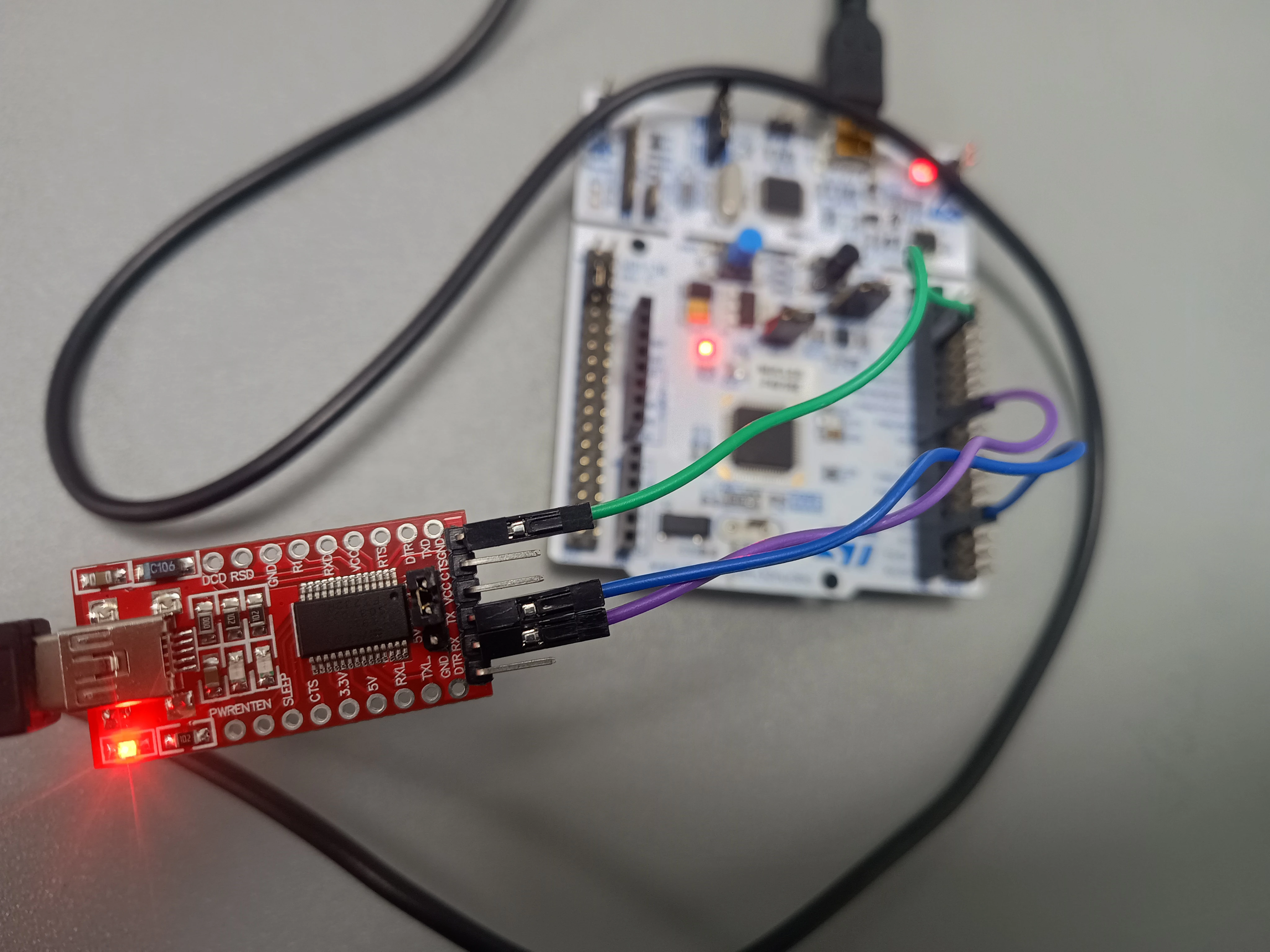
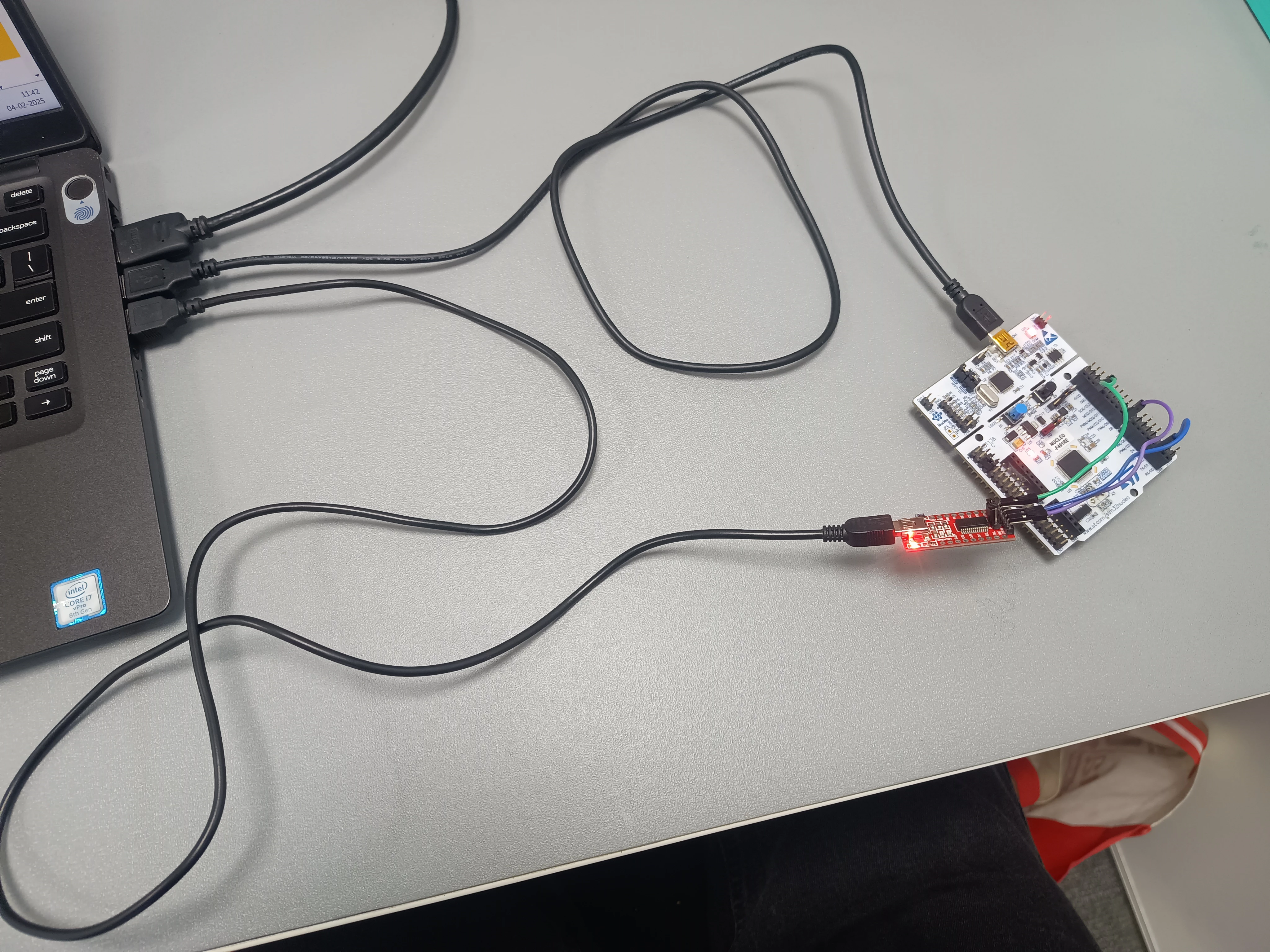
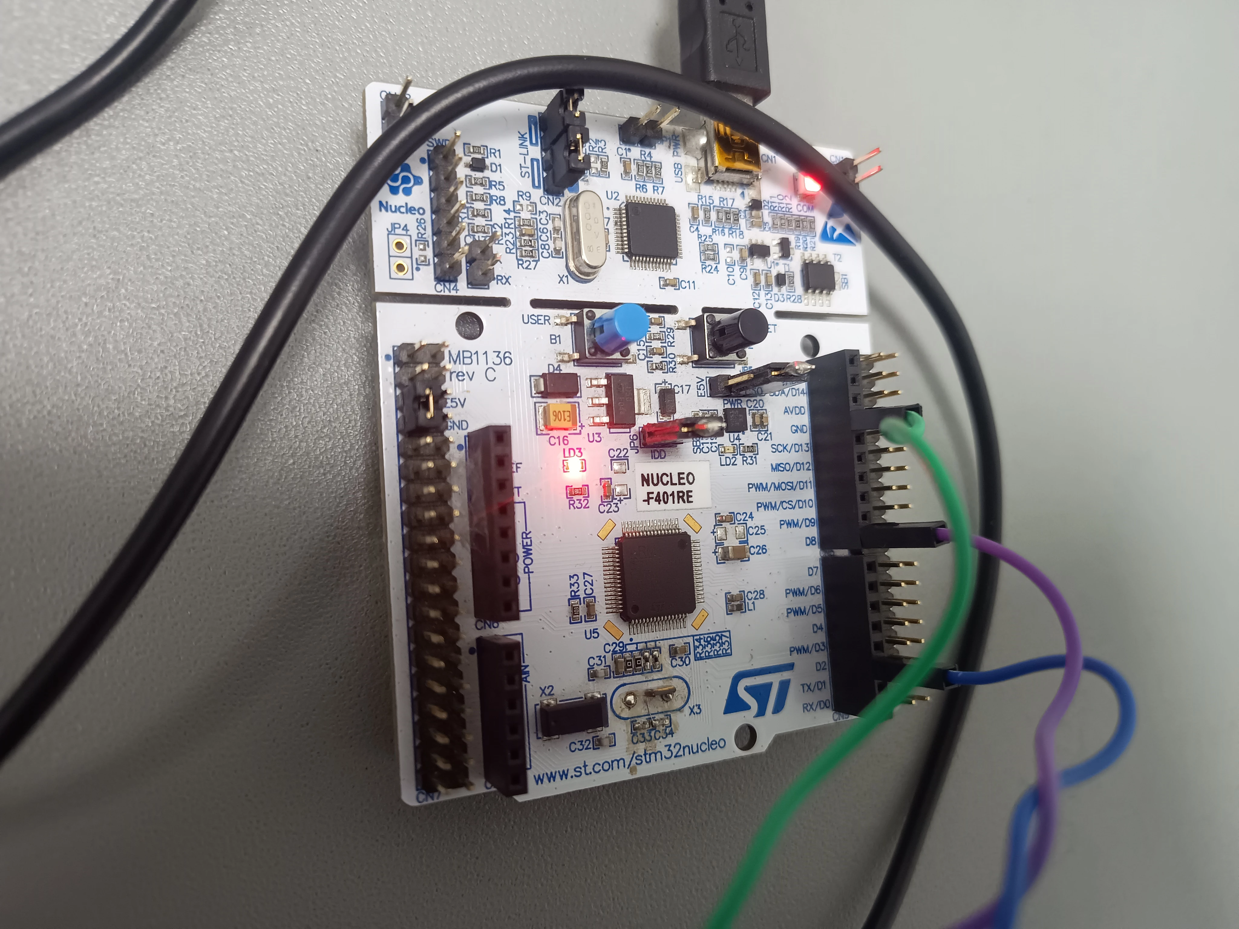
USART1_stmconnectionUSART1_stmconnectionUSART1_FTDIconnectionUSART1_FTDIconnectionpower supplypower supply

Connecting to the UART Bootloader on STM32

After much trial and error, I successfully connected to the UART bootloader on the STM32. Below are the steps I followed:

  1. Connect the USART1_RX pin of the STM32 to the TX pin of the FTDI module.
  2. Connect the USART1_TX pin of the STM32 to the RX pin of the FTDI module.
  3. Ensure a common ground between the STM32 and the FTDI module.
  4. Set the BOOT0 pin high to enter boot mode by connecting it to the VDD pin (do not use any other pin).
  5. Power the STM32 via USB by connecting it to your host, and also power the FTDI module via USB by connecting it to your host.
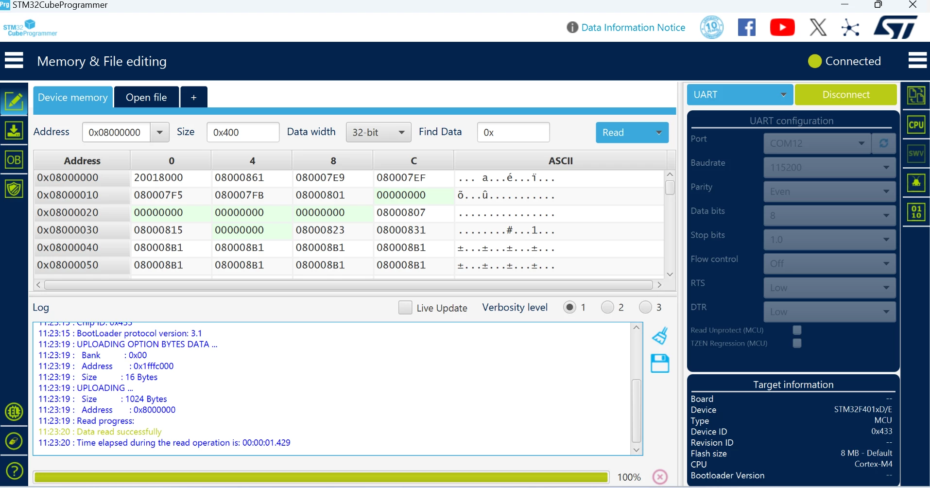
  6. Open Device Manager and locate the FTDI module’s port (not the STM32 port). Select that port in STM32CubeProgrammer, set the baud rate to 115200, parity to even, and tap on connect. It should connect successfully.

Q1: Why was I experiencing errors and unable to connect my UART Bootloader?

Answer: Initially, I was powering the FTDI module using the STM32 by connecting the VCC of the FTDI to the VCC of the STM32. While this can work if your power output is adequate, to avoid the issues I faced, I recommend powering the FTDI module directly from the host. Ensure you have a common ground between the STM32 and the FTDI module.


I hope this helps the community!  and special thanks to the @Andrew Neil and @mƎALLEm 

21 replies

Andrew Neil
Super User
January 27, 2025

Welcome to the forum

I'm not entiorely clear what you're actually asking:

  • Your title suggests that you want to upload code via a UART;
  • But the post sounds more like you just want to control the blinking via a UART?


A complex system that works is invariably found to have evolved from a simple system that worked.A complex system designed from scratch never works and cannot be patched up to make it work.
mohite25Author
Associate II
January 27, 2025

Yes, my main task is that I want to upload the firmware via uart because stlink is connected to the uart2. and I want to use the other uart. that's why inquiring about how I can upload the code via another uart and bipass the st-link?


Andrew Neil
Super User
January 27, 2025

@mohite25 wrote:

I want to upload the firmware via uart because stlink is connected to the uart2.


That doesn't really make sense.

The ST-Link has two connections to the Target microcontroller:

  1. The SWD connection - used for programming and debugging;
  2. A separate UART connection.

So using the ST-Link for programming (downloading) does not preclude using the UART for comms.

AndrewNeil_1-1737979624124.png


PS:

Or, if you want to disconnect that UART from the ST-Link, you can do that and still retain the SWD programming connection.

A complex system that works is invariably found to have evolved from a simple system that worked.A complex system designed from scratch never works and cannot be patched up to make it work.
mƎALLEm
ST Technical Moderator
January 27, 2025

Hello @mohite25 and welcome to the community,

Need to refer first to the AN2606 / Section 31 STM32F401xD(E) devices:

These are the USARTs and theirs respective pins that you can use with the bootloader for this product:

SofLit_0-1737978853880.png

And you cannot use other pins.

Hope that helps.


To give better visibility on the answered topics, please click "Best answer" on the reply which solved your issue or answered your question.
mohite25Author
Associate II
January 27, 2025

Thank you, @mƎALLEm, for taking the time to answer my question! I really appreciate your help.

Based on the guidance in AN260, I have followed the necessary steps to use USART1 for communication. Here’s what I have done so far:

  • I connected UART1_TX of the STM32 to the RX pin of the FTDI module and UART1_RX to the TX pin of the FTDI module.
  • The VDD pin of the STM32 is connected to the FTDI module to ensure proper power supply.
  • A common ground is established between the Nucleo board and the FTDI module.
  • To enter boot mode, I set the BOOT0 pin to HIGH by connecting it to the E5V pin using a jumper cable.

After making these connections, I connect the FTDI module to my laptop and follow these steps:

  1. Press the reset button on the STM32 board.
  2. Open STM32CubeProgrammer, select UART mode, and choose the correct COM port and baud rate settings.
  3. Click the Connect button.

However, despite following these steps, I am still encountering an error. Could you please help me troubleshoot this issue? Any suggestions would be greatly appreciated!

Andrew Neil
Super User
January 27, 2025

@mohite25 wrote:

However, despite following these steps, I am still encountering an error. Could you please help me troubleshoot this issue? 


For a start, you'd need to say what error, exactly, you are encountering.

Please post a screenshot showing the error(s) and/or copy & paste the error text.

For pasting error text, see: https://community.st.com/t5/community-guidelines/how-to-write-your-question-to-maximize-your-chances-to-find-a/tac-p/725146/highlight/true#M54

Also show your connections between the Nucleo board and the FTDI UART-to-USB converter.


I'm still unclear why you want to go through all the hassle of using a UART when you have a perfectly good ST-Link which will do it far more conveniently via the SWD connection?

A complex system that works is invariably found to have evolved from a simple system that worked.A complex system designed from scratch never works and cannot be patched up to make it work.
mohite25AuthorBest answer
Associate II
February 4, 2025


mohite25_0-1738649452294.png

USART1_stmconnectionUSART1_stmconnectionUSART1_FTDIconnectionUSART1_FTDIconnectionpower supplypower supply

Connecting to the UART Bootloader on STM32

After much trial and error, I successfully connected to the UART bootloader on the STM32. Below are the steps I followed:

  1. Connect the USART1_RX pin of the STM32 to the TX pin of the FTDI module.
  2. Connect the USART1_TX pin of the STM32 to the RX pin of the FTDI module.
  3. Ensure a common ground between the STM32 and the FTDI module.
  4. Set the BOOT0 pin high to enter boot mode by connecting it to the VDD pin (do not use any other pin).
  5. Power the STM32 via USB by connecting it to your host, and also power the FTDI module via USB by connecting it to your host.
  6. Open Device Manager and locate the FTDI module’s port (not the STM32 port). Select that port in STM32CubeProgrammer, set the baud rate to 115200, parity to even, and tap on connect. It should connect successfully.

Q1: Why was I experiencing errors and unable to connect my UART Bootloader?

Answer: Initially, I was powering the FTDI module using the STM32 by connecting the VCC of the FTDI to the VCC of the STM32. While this can work if your power output is adequate, to avoid the issues I faced, I recommend powering the FTDI module directly from the host. Ensure you have a common ground between the STM32 and the FTDI module.


I hope this helps the community!  and special thanks to the @Andrew Neil and @mƎALLEm