Turn on suggestions
Auto-suggest helps you quickly narrow down your search results by suggesting possible matches as you type.
Showing results for
- STMicroelectronics Community
- STM32 MCUs
- STM32 MCUs Products
- Re: STM32H753XI MCU with W25Q512 in dual flash mod...
Options
- Subscribe to RSS Feed
- Mark Topic as New
- Mark Topic as Read
- Float this Topic for Current User
- Bookmark
- Subscribe
- Mute
- Printer Friendly Page
STM32H753XI MCU with W25Q512 in dual flash mode
Options
- Mark as New
- Bookmark
- Subscribe
- Mute
- Subscribe to RSS Feed
- Permalink
- Email to a Friend
- Report Inappropriate Content
2023-06-21 12:08 AM
Hello,
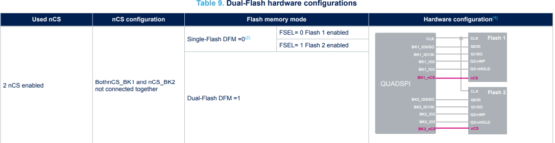
I'm using STM32H753XI MCU with two W25Q512JV(its 64Mb) in dual mode, the nCS and data lines are separate, Clock line is same. I've configured the QUAD SPI in dual flash mode as mentioned in AN4760. I'm trying to read the sectors from first flash then I see that the alternate bytes are not read correctly.
  hqspi.Instance = QUADSPI;
  hqspi.Init.ClockPrescaler = 2;
  hqspi.Init.FifoThreshold = 4;
  hqspi.Init.SampleShifting = QSPI_SAMPLE_SHIFTING_HALFCYCLE;
  hqspi.Init.FlashSize = 31;
  hqspi.Init.ChipSelectHighTime = QSPI_CS_HIGH_TIME_1_CYCLE;
  hqspi.Init.ClockMode = QSPI_CLOCK_MODE_0;
  hqspi.Init.FlashID = QSPI_FLASH_ID_1;
  hqspi.Init.DualFlash = QSPI_DUALFLASH_ENABLE;
  if (HAL_QSPI_Init(&hqspi) != HAL_OK)
  {
    Error_Handler();
  }
Next, I've tried using single flash at a time with FSEL bit, I'm able to read the data from one flash only. second flash write/ read operation is not happening.
Am I missing some configuration part?
Thanks,
7 REPLIES 7
Options
- Mark as New
- Bookmark
- Subscribe
- Mute
- Subscribe to RSS Feed
- Permalink
- Email to a Friend
- Report Inappropriate Content
2023-06-21 08:42 AM
Hello @AShel.1 ,
When the Dual-flash mode enabled (DFM = 1), the FSEL bit is ignored.
Could you please check the ChipSelectHighTime in the datasheet memory .
Thank you.
Kaouthar
To give better visibility on the answered topics, please click on Accept as Solution on the reply which solved your issue or answered your question.
Options
- Mark as New
- Bookmark
- Subscribe
- Mute
- Subscribe to RSS Feed
- Permalink
- Email to a Friend
- Report Inappropriate Content
2023-07-03 09:44 PM
Hello,
yes, when I've enabled DFM mode then I'm not using FSEL bit.
on ChipSelectHighTime, I've referred the settings from this example, also I've tried different combinations of chip select.
https://github.com/Crazy-Geeks/STM32-W25Q-QSPI/tree/main
I'm trying dual bank memory mapped sample code from STM32Cube repository,
  QSPIHandle.Instance = QUADSPI;

  /* QSPI initialization */
  /* ClockPrescaler set to 1, so QSPI clock = 200MHz / (1+1) = 100MHz */
  QSPIHandle.Init.ClockPrescaler     = 1;
  QSPIHandle.Init.FifoThreshold      = 1;
  QSPIHandle.Init.SampleShifting     = QSPI_SAMPLE_SHIFTING_HALFCYCLE;
  QSPIHandle.Init.FlashSize          = QSPI_FLASH_SIZE;
  QSPIHandle.Init.ChipSelectHighTime = QSPI_CS_HIGH_TIME_3_CYCLE;
  QSPIHandle.Init.ClockMode          = QSPI_CLOCK_MODE_0;
  QSPIHandle.Init.DualFlash          = QSPI_DUALFLASH_ENABLE;

  sCommand.InstructionMode   = QSPI_INSTRUCTION_1_LINE;
  sCommand.AddressSize       = QSPI_ADDRESS_32_BITS;
  sCommand.AlternateByteMode = QSPI_ALTERNATE_BYTES_NONE;
  sCommand.DdrMode           = QSPI_DDR_MODE_DISABLE;
  sCommand.DdrHoldHalfCycle  = QSPI_DDR_HHC_ANALOG_DELAY;
  sCommand.SIOOMode          = QSPI_SIOO_INST_EVERY_CMD;

  while(1)
  {
    switch(step)
    {
      case 0:
        CmdCplt = 0;

        /* Initialize QuadSPI ------------------------------------------------ */
        HAL_QSPI_DeInit(&QSPIHandle);
        if (HAL_QSPI_Init(&QSPIHandle) != HAL_OK)
        {
          Error_Handler();
        }

        /* Enable 4 bytes Address mode */
        QSPI_EnterFourBytesAddress(&QSPIHandle);

        HAL_Delay(10);
        /* Enable write operations ------------------------------------------- */
        QSPI_WriteEnable(&QSPIHandle);

        /* Erasing Sequence -------------------------------------------------- */
        sCommand.Instruction = SECTOR_ERASE_CMD;
        sCommand.AddressMode = QSPI_ADDRESS_1_LINE;
        sCommand.Address     = address;
        sCommand.DataMode    = QSPI_DATA_NONE;
        sCommand.DummyCycles = 0;

        if (HAL_QSPI_Command_IT(&QSPIHandle, &sCommand) != HAL_OK)
        {
          Error_Handler();
        }

        step++;
        break;

      case 1:
        if(CmdCplt != 0)
        {
          CmdCplt = 0;
          StatusMatch = 0;

          /* Configure automatic polling mode to wait for end of erase ------- */
          QSPI_AutoPollingMemReady(&QSPIHandle);

          step++;
        }
        break;

      case 2:
        if(StatusMatch != 0)
        {
          StatusMatch = 0;
          TxCplt = 0;

          /* Enable write operations ----------------------------------------- */
          QSPI_WriteEnable(&QSPIHandle);

          /* Writing Sequence ------------------------------------------------ */
          sCommand.Instruction = QUAD_IN_FAST_PROG_CMD;
          sCommand.AddressMode = QSPI_ADDRESS_1_LINE;
          sCommand.DataMode    = QSPI_DATA_4_LINES;
          sCommand.NbData      = BUFFERSIZE;

          if (HAL_QSPI_Command(&QSPIHandle, &sCommand, HAL_QPSI_TIMEOUT_DEFAULT_VALUE) != HAL_OK)
          {
            Error_Handler();
          }

          if (HAL_QSPI_Transmit_IT(&QSPIHandle, aTxBuffer) != HAL_OK)
          {
            Error_Handler();
          }

          step++;
        }
        break;

      case 3:
        if(TxCplt != 0)
        {
          TxCplt = 0;
          StatusMatch = 0;

          /* Configure automatic polling mode to wait for end of program ----- */
          QSPI_AutoPollingMemReady(&QSPIHandle);

          step++;
        }
        break;

      case 4:
        if(StatusMatch != 0)
        {
          StatusMatch = 0;
          RxCplt = 0;

          /* Configure Volatile Configuration register (with new dummy cycles) */
          QSPI_DummyCyclesCfg(&QSPIHandle);

          /* Reading Sequence ------------------------------------------------ */
          sCommand.Instruction = QUAD_OUT_FAST_READ_CMD;
          sCommand.DummyCycles = DUMMY_CLOCK_CYCLES_READ_QUAD;

          sMemMappedCfg.TimeOutActivation = QSPI_TIMEOUT_COUNTER_DISABLE;

          if (HAL_QSPI_MemoryMapped(&QSPIHandle, &sCommand, &sMemMappedCfg) != HAL_OK)
          {
            Error_Handler();
          }

          for (index = 0; index < BUFFERSIZE; index++)
          {
            if (*qspi_addr != aTxBuffer[index])
            {
              BSP_LED_On(LED3);
            }
            qspi_addr++;
          }
          BSP_LED_Toggle(LED1);

          address += QSPI_PAGE_SIZE;
          if(address >= QSPI_END_ADDR)
          {
            address = 0;
          }
          qspi_addr = (__IO uint8_t *)(0x90000000 + address);

          step = 0;
        }
        break;

      default :
        Error_Handler();
    }
  }
this example works fine for dual bank, it performs QSPI_Init->Erase->Write->Read operation, I'm not sure why it needs to re-initialize QSPI every time, if I take the QSPI init function out of the while loop, only one cycle of Erase->Write->Read operation is performed and it goes into ErrorHandler state in second cycle Erase function because the HAL is busy in HAL_QSPI_STATE_BUSY_MEM_MAPPED.
I've tried to force the hqspi->state to HAL_QSPI_STATE_READY but it still gives error.
Options
- Mark as New
- Bookmark
- Subscribe
- Mute
- Subscribe to RSS Feed
- Permalink
- Email to a Friend
- Report Inappropriate Content
2023-07-04 04:02 AM
If I erase->write->read same sector then it works fine, if I erase->write->read same sector -> read another sector then I get valid data from same sector but another sector reads 0xFF, this another sector was written successfully in earlier cycle. so to read data consecutively from different sectors is there any special command to be used?
here is my Read function,
uint8_t QUADSPI_Read(uint8_t* pData, uint32_t ReadAddr, uint32_t Size)
{
  QSPI_CommandTypeDef s_command;
	QSPI_DummyCyclesCfg(&hqspi);
	s_command.InstructionMode   = QSPI_INSTRUCTION_1_LINE;
  	s_command.Instruction       = QUAD_OUT_FAST_READ_CMD;
  	s_command.AddressSize       = QSPI_ADDRESS_32_BITS;//QSPI_ADDRESS_24_BITS;
  	s_command.AddressMode       = SPI_ADDRESS_1_LINE;//QSPI_ADDRESS_4_LINES;//
        s_command.Address           = ReadAddr;
        s_command.AlternateByteMode = QSPI_ALTERNATE_BYTES_NONE;
        s_command.DataMode          = QSPI_DATA_4_LINES;
        s_command.DummyCycles       = DUMMY_CYCLES_READ_QUAD;//8 cycles
        s_command.NbData            = Size;
        s_command.DdrMode           = QSPI_DDR_MODE_DISABLE;
        s_command.DdrHoldHalfCycle  = QSPI_DDR_HHC_ANALOG_DELAY;
        s_command.SIOOMode          = QSPI_SIOO_INST_EVERY_CMD;

  /* Configure the command */
  if (HAL_QSPI_Command(&hqspi, &s_command, HAL_QPSI_TIMEOUT_DEFAULT_VALUE) != HAL_OK)
  {
    return QSPI_ERROR;
  }

  /* Set S# timing for Read command */
  //MODIFY_REG(hqspi.Instance->DCR, QUADSPI_DCR_CSHT, QSPI_CS_HIGH_TIME_3_CYCLE);
  /* Reception of the data */

  if (HAL_QSPI_Receive(&hqspi, pData, HAL_QPSI_TIMEOUT_DEFAULT_VALUE) != HAL_OK)
    {
      return QSPI_ERROR;
    }

  /* Restore S# timing for nonRead commands */
  //MODIFY_REG(hqspi.Instance->DCR, QUADSPI_DCR_CSHT, QSPI_CS_HIGH_TIME_6_CYCLE);

  return QSPI_OK;
}Options
- Mark as New
- Bookmark
- Subscribe
- Mute
- Subscribe to RSS Feed
- Permalink
- Email to a Friend
- Report Inappropriate Content
2023-07-04 06:26 AM - edited 2023-07-04 06:33 AM
In Dual Mode the thing to consider is that everything doubles in size. The erase blocks which were 4KB will be effectively be 8KB. You'll need to be conscious of this as the step distance for the addressing expands along with the expectations for writes and erases.
The status read will also need to be double-wide and both devices will need to report ready/not-busy. The devices are not synchronized, so the erases and writes on each device might complete at different times, and may be content specific/related.
Tips, Buy me a coffee, or three.. PayPal Venmo
Up vote any posts that you find helpful, it shows what's working..
Up vote any posts that you find helpful, it shows what's working..
Options
- Mark as New
- Bookmark
- Subscribe
- Mute
- Subscribe to RSS Feed
- Permalink
- Email to a Friend
- Report Inappropriate Content
2023-07-04 06:32 AM
Thanks for the quick response, would you please provide me some example to handle this kind of case.
Options
- Mark as New
- Bookmark
- Subscribe
- Mute
- Subscribe to RSS Feed
- Permalink
- Email to a Friend
- Report Inappropriate Content
2023-07-04 06:45 AM
If you're deblocking at 4KB, 32KB or 64KB then you'll need to expand those to 8KB, 64KB and 128KB
Perhaps look at the QSPI examples for the DISCO and EVAL boards, and where the polling operations operate on two bytes wide rather than one.
Remember you're talking to TWO chips, and the content is being interleaved at a byte level.
Tips, Buy me a coffee, or three.. PayPal Venmo
Up vote any posts that you find helpful, it shows what's working..
Up vote any posts that you find helpful, it shows what's working..
Options
- Mark as New
- Bookmark
- Subscribe
- Mute
- Subscribe to RSS Feed
- Permalink
- Email to a Friend
- Report Inappropriate Content
2023-07-30 09:59 PM
This solution is working for STM32H753 Eval board but on my target board we've Winbond ICs wherein the same configuration did not work, I see right data read from first flash but the second flash reads 0x99 value.