Turn on suggestions
Auto-suggest helps you quickly narrow down your search results by suggesting possible matches as you type.
Showing results for
- STMicroelectronics Community
- STM32 MCUs
- STM32 MCUs Products
- STM32G431 Bootloader issue
Options
- Subscribe to RSS Feed
- Mark Topic as New
- Mark Topic as Read
- Float this Topic for Current User
- Bookmark
- Subscribe
- Mute
- Printer Friendly Page
STM32G431 Bootloader issue

Options
- Mark as New
- Bookmark
- Subscribe
- Mute
- Subscribe to RSS Feed
- Permalink
- Email to a Friend
- Report Inappropriate Content
2026-05-06 4:52 AM
Hi,
I have a problem with a custom board, where i can not enter bootloader, on some boards...
I had a production where around 10% has this issue. (I did not see it on earlier production of 5pcs).
The problem is the cube programmer will not enter bootloader mode.
I use a autodirection rs485 tranciever (5V on FT pins) and it is working on many of the boards with no problem, also the in-application code works fine for modbus (also on the bootloader broken devices, after programming with ST-Link)
I am using a FTDI USB to RS485 converter.
The boot pin is held up by a hall sensor and inverter transistor, i have noticed these sensors has different startup time 50-100ms - therefore the MCU reset pin is controlled by a rather slow RC circuit, to ensure boot is high before reset is released. (this is a litle risky).
However, i can see on the current consumption when it goes into application mode or assumed bootloader mode, as in bootloader mode the current stays much lower.
I can see on the RX pin of the tranciever it recieves the 0x7F from cube programmer and i can measure it close to the MCU pin (UFQFPN). But there is none answer from the MCU on TX pin.
Remember the communication is working without errors in application mode, also only with autodirection.
I have tried to short the boot0 to 3V3 with same result, i have tried to have long and short reset pulse time, same result...
I have sometimes managed to get the failing board to enter the bootloader, and then it does it several times in a row, but will stop work again.
I have tried to run the PC of battery, short the pc and lab psu together to ensure common mode voltage, but the recieved signal out of the tranciever looks good, and equal to a working device, i calculated baudrate/timing and it was ok...
I have chatted with AI during the process and asked it to make a summery there is below.
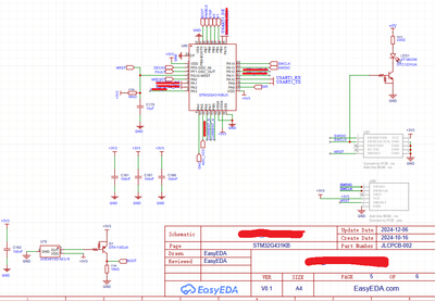
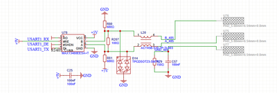
There is added pullup between pin 2 & 3 on the rs485 tranciever 10K.
I really do find this strange, i have been thinking about noise on pins there keeps the bootloader IRQ too busy.. but have not seen such thing.
I have not changed any options bytes, i have checked the Boot1 flag and the SWboot flag, not changed and seems correct.
There seems no glitches on the supply lines.
Boards are produced by JLC, could there be counterfight chips?
I have worked with STM MCU for many years, but this issue seems new to me...
I hope you can give me some hints
Thanks
AI content:
STM32G431 UART Bootloader (RS485) – Intermittent No-Response on 0x7F (4/40 boards)
🧩 MCU / Setup
- MCU: STM32G431KNU3
- Interface: UART bootloader via RS485
- Transceiver: MAX13488
- Baudrate: 9600
- Boot mode: BOOT0 = HIGH (forced to 3.3V)
- Reset: external NRST pin
:magnifying_glass_tilted_left: Problem Summary
Out of 40 identical boards:
- ~36 boards: bootloader works reliably
- ~4 boards: bootloader does NOT respond to 0x7F
- Same failing boards can sometimes work after repeated resets
:satellite_antenna: Observations
UART signal
- 0x7F waveform verified on MCU RX pin
- Clean edges (fast rise/fall)
- Low level < 0.5V
- High level ≈ 5.0–5.2V (pin is 5V tolerant)
- Minimal ringing observed
Timing
- Measured ~832 µs from start bit to end of 7 data bits → matches 9600 baud
- No baud mismatch observed
Behavior
- MCU does enter bootloader mode (verified via current consumption):
- ~6–7 mA in bootloader
- ~15 mA in application
- However:
- No response to 0x7F (no ACK) on failing units
:repeat_button: Reset / Boot Experiments
Tested:
- BOOT0 tied directly to 3.3V → no change
- Removed reset capacitor → NRST via 100k pull-up → no change
- Verified BOOT0 is stable before reset release
- Reset pulse manually applied → sometimes enables successful connection
Observations:
- Reset timing influences success rate
- Behavior is non-deterministic per reset
:electric_plug: RS485 / Hardware Details
- RS485 auto-direction enabled via:
- PB3 connected to TX enable control
- 10k pull-up used to default direction
- Important:
- PB3 is floating during bootloader (GPIO default state)
- External circuit defines transceiver state
- Verified:
- 0x7F passes correctly through transceiver
- Signal integrity looks correct on both TTL and differential sides
:cross_mark: What has been ruled out
- Signal integrity issues (clean waveform)
- Baudrate mismatch
- BOOT0 instability
- Slow reset RC ramp
- Noise/ringing on RX line
- Incorrect pin mapping
- Firmware interference (bootloader mode confirmed active)
- GPIO conflicts / interrupts (boot ROM context)
:warning: Suspected Root Causes
Based on observations, likely candidates:
1. UART bootloader autobaud timing sensitivity
- Bootloader may miss or misinterpret first 0x7F
- Possible dependency on exact timing of first edge
2. UART RX enable timing in boot ROM
- First byte may arrive before UART is fully ready
3. RS485 transceiver direction timing
- Auto-direction may not be in correct state during first byte
- Potential subtle contention or delay not visible on scope
4. Internal clock (HSI) startup variation
- May affect autobaud measurement
:question_mark: Questions for ST
- Is there any known errata regarding:
- UART bootloader autobaud reliability on STM32G4?
- Sensitivity to first byte timing?
- How long after reset is UART guaranteed to be ready in system bootloader?
- Is it required to delay sending 0x7F after reset?
- If yes, recommended delay?
- Does the bootloader retry autobaud if first byte is missed?
- Any known interaction issues with half-duplex (RS485) setups?
🧪 Additional Notes
- Issue is reproducible on same subset of boards
- Boards are otherwise fully functional in application mode
- UART works perfectly at 9600 baud in user firmware
- No visible hardware defects
Labels:
- Labels:
-
Bootloader
-
STM32G4 Series
5 REPLIES 5

Options
- Mark as New
- Bookmark
- Subscribe
- Mute
- Subscribe to RSS Feed
- Permalink
- Email to a Friend
- Report Inappropriate Content
2026-05-06 2:59 PM
On a board that has the problem, plot BOOT0, NRST, and UART_TX, UART_RX on a scope. You will find the issue.
If you feel a post has answered your question, please click "Accept as Solution".
Options
- Mark as New
- Bookmark
- Subscribe
- Mute
- Subscribe to RSS Feed
- Permalink
- Email to a Friend
- Report Inappropriate Content
2026-05-06 10:00 PM
Hi,
Thanks for your time.
Agree, and indeed i have done it, i did not save the pictures, but will make a new set to post.
For the RX/TX, on TTL level, Trigger on RX, the signal starts high, then there is a single start bit, and in the end before the high stop bit there is the 1 bit low... It is 5V signal, have nice edges and low level below 0.5V.
according to chatty the timing fits, from first falling to last falling and 8bit time.
On TX pin there never comes any signal :(
For the Boot0 vs NRST, as you can see by the RC timing the reset raises slowly.
The time Boot0 goes high the NRST has been seen between 0.7 to 1V, remember the NRST has the schmidt trigger.
However i was afraid this was the problems, so have tried with same result to connect boot0 to 3.3V, and afterward to remove the big reset cap (with boot0 high) and still issue.
I have also probed a working board and TX comes quite soon after the 0x7C.
There has been seen a little noise on the signals, but for now i blaimed the probes and grounding in measurement, but it as i recall was maximum +/-50-100mV.
Also remember the current consumption tells atleast it does not go into normal flash execution, as the current consumption is ~15mA - where when the boot0 signal is applied it is around 0-5mA


Options
- Mark as New
- Bookmark
- Subscribe
- Mute
- Subscribe to RSS Feed
- Permalink
- Email to a Friend
- Report Inappropriate Content
2026-05-07 1:17 AM
While the factory bootloader does not have published sources, you still can connect a debugger and observe activity in the registers.
Couldn't this be the case where activity on other pins falsely starts bootloading on a different interface than the intended one?
JW
Options
- Mark as New
- Bookmark
- Subscribe
- Mute
- Subscribe to RSS Feed
- Permalink
- Email to a Friend
- Report Inappropriate Content
2026-05-07 2:37 AM
Hi,
I have been thinking of exactly this.
But the information i have seen, not sure they are correct, but they have to recieve and verify the byte.
But thanks for the heads up, let me try to do so...
Kasper
Options
- Mark as New
- Bookmark
- Subscribe
- Mute
- Subscribe to RSS Feed
- Permalink
- Email to a Friend
- Report Inappropriate Content
2026-05-07 2:54 AM
Thanks to autobaud, quite wide range of signals may seem as a valid "starting" byte on the UART interface (btw. autobaud may also lead to false baudrate detection with the given UART, if there's some noise before the "legitimate" starting byte). I'm not sure what does it take the other interfaces to get activated, but once they do (perhaps on a single clock pulse), they may hang there waiting for more, with or without timeout...
JW

Related Content
- STM32H743 and STM32H745 Embedded Bootloader Version Upgrade - V9.1 to V9.2 in STM32 MCUs Products
- STM32H743VGT6 flash memory in STM32 MCUs Products
- STM32H5 can only connect in HotPlug mode. in STM32 MCUs Boards and hardware tools
- STM32H743 USB Host MSC + FATFS f_opendir() Deadlock Issue in Bootloader in STM32 MCUs Embedded software
- MCU won't restart after setting RDP level 1 at startup on U575 in STM32 MCUs Security