Question
SPI Transmitting and Receiving Data Not Matching
Hello,
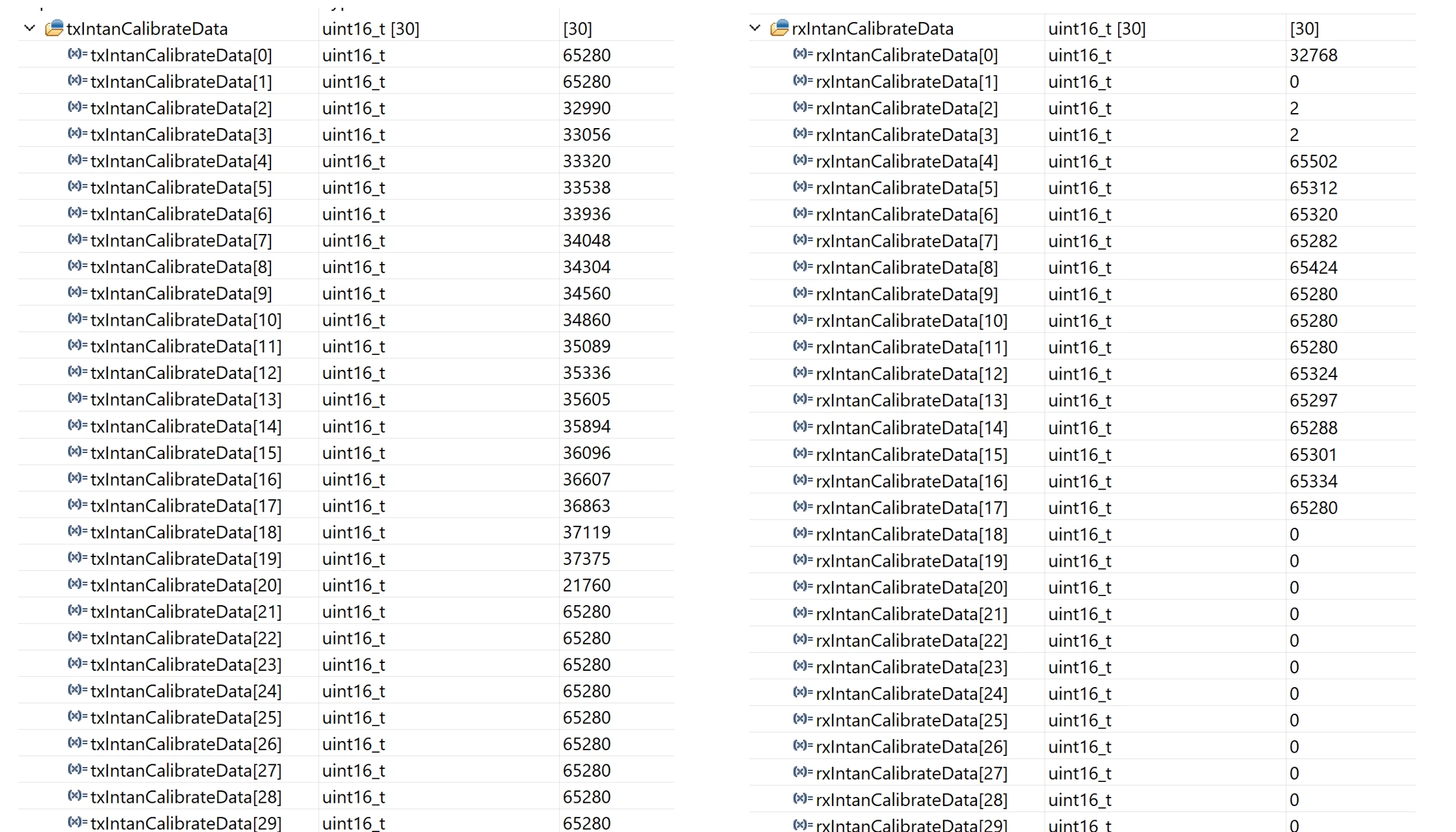
I control an ADC with SPI interface of the STM32F44 microcontroller. The ADC datasheet is in the link, https://intantech.com/files/Intan_RHD2000_series_datasheet.pdf . I set up global variables as read, write, and calibrate masks. The I call them with certain sequence based on the datasheet suggestions. But based on the transmitting values, the receiving value are not matching? For example, how the rx..[2]=2 is possible? Do you have any suggestion about the problem?
// Intan READ WRITE CONVERT CALIBRATE masks
uint16_t ReadCommandMask = 0b1100000000000000;
uint16_t WriteCommandMask = 0b1000000000000000;
uint16_t ConvertCommandMask = 0b0000000000000001;
uint16_t CalibrateCommandMask = 0b0101010100000000;

//INTAN Register Settings
	 		 txIntanCalibrateData[0] = ReadCommandMask | (63 << 8); // Reg 63, used as a dummy read
	 		 txIntanCalibrateData[1] = ReadCommandMask | (63 << 8); // Reg 63, used as a dummy read
	 		 txIntanCalibrateData[2] = WriteCommandMask | (0 << 8) | 0xDE; // Reg 0 settings
	 		 txIntanCalibrateData[3] = WriteCommandMask | (1 << 8) | 0x20; // Reg 1 settings
	 		 txIntanCalibrateData[4] = WriteCommandMask | (2 << 8) | 0x28; // Reg 2 settings
	 		 txIntanCalibrateData[5] = WriteCommandMask | (3 << 8) | 0x02; // Reg 3 settings
	 		 txIntanCalibrateData[6] = WriteCommandMask | (4 << 8) | 0x90; // Reg 4 settings
	 		 txIntanCalibrateData[7] = WriteCommandMask | (5 << 8) | 0x00; // Reg 5 settings
	 		 txIntanCalibrateData[8] = WriteCommandMask | (6 << 8) | 0x00; // Reg 6 settings
	 		 txIntanCalibrateData[9] = WriteCommandMask | (7 << 8) | 0x00; // Reg 7 settings
	 		 txIntanCalibrateData[10] = WriteCommandMask | (8 << 8) | 0x2C; // Reg 8 settings
	 		 txIntanCalibrateData[11] = WriteCommandMask | (9 << 8) | 0x11; // Reg 9 settings
	 		 txIntanCalibrateData[12] = WriteCommandMask | (10 << 8) | 0x08; // Reg 10 settings
	 		 txIntanCalibrateData[13] = WriteCommandMask | (11 << 8) | 0x15; // Reg 11 settings
	 		 txIntanCalibrateData[14] = WriteCommandMask | (12 << 8) | 0x36; // Reg 12 settings
	 		 txIntanCalibrateData[15] = WriteCommandMask | (13 << 8) | 0x00; // Reg 13 settings
	 		 txIntanCalibrateData[16] = WriteCommandMask | (14 << 8) | 0xFF; // Reg 14 settings
	 		 txIntanCalibrateData[17] = WriteCommandMask | (15 << 8) | 0xFF; // Reg 15 settings
	 		 txIntanCalibrateData[18] = WriteCommandMask | (16 << 8) | 0xFF; // Reg 16 settings
	 		 txIntanCalibrateData[19] = WriteCommandMask | (17 << 8) | 0xFF; // Reg 17 settings
	 		 txIntanCalibrateData[20] = CalibrateCommandMask; // Calibrate
	 		 txIntanCalibrateData[21] = ReadCommandMask | (63 << 8); // Reg 63, used as a dummy read
	 		 txIntanCalibrateData[22] = ReadCommandMask | (63 << 8); // Reg 63, used as a dummy read
	 		 txIntanCalibrateData[23] = ReadCommandMask | (63 << 8); // Reg 63, used as a dummy read
	 		 txIntanCalibrateData[24] = ReadCommandMask | (63 << 8); // Reg 63, used as a dummy read
	 		 txIntanCalibrateData[25] = ReadCommandMask | (63 << 8); // Reg 63, used as a dummy read
	 		 txIntanCalibrateData[26] = ReadCommandMask | (63 << 8); // Reg 63, used as a dummy read
	 		 txIntanCalibrateData[27] = ReadCommandMask | (63 << 8); // Reg 63, used as a dummy read
	 		 txIntanCalibrateData[28] = ReadCommandMask | (63 << 8); // Reg 63, used as a dummy read
	 		 txIntanCalibrateData[29] = ReadCommandMask | (63 << 8); // Reg 63, used as a dummy read

for (int i = 0; i < 30; i++) {
	 			 HAL_GPIO_WritePin(INTAN_SPI2_CS_GPIO_Port, INTAN_SPI2_CS_Pin, GPIO_PIN_RESET);
	 			 hal_status = HAL_SPI_TransmitReceive(&hspi2, (uint8_t*) &txIntanCalibrateData[i], (uint8_t*) &rxIntanCalibrateData[i], 1, 100);
	 			 HAL_GPIO_WritePin(INTAN_SPI2_CS_GPIO_Port, INTAN_SPI2_CS_Pin, GPIO_PIN_SET);
	 			 HAL_Delay(100);
	 			 if (hal_status != HAL_OK) {
	 			 	 printf("HAL SPI TransmitReceive error: %d\r\n", (int) hal_status);
	 			 }
	 		 }