Turn on suggestions
Auto-suggest helps you quickly narrow down your search results by suggesting possible matches as you type.
Showing results for
- STMicroelectronics Community
- Product forums
- Analog and audio
- Re: Poblem with LM358DT and not with LM324AD
Options
- Subscribe to RSS Feed
- Mark Topic as New
- Mark Topic as Read
- Float this Topic for Current User
- Bookmark
- Subscribe
- Mute
- Printer Friendly Page
Poblem with LM358DT and not with LM324AD
Options
- Mark as New
- Bookmark
- Subscribe
- Mute
- Subscribe to RSS Feed
- Permalink
- Email to a Friend
- Report Inappropriate Content
2024-03-21 5:42 AM - edited 2024-03-21 6:20 AM
Dear all, the first of all thanks for let me leave a message in this post.
We have a schematic circuit, with the LM324 it works but with the LM358 doesn´t work. It gives the correct voltage in both chips in the output, I connect a relay solid state from Carlos Gavazi and with the LM324 works and with the LM358 doesn`t works. the differents inside the chips are ( picture attach).
I check the mA output and all is correct. the consume of solid state relay is only 10mA
Somebody have this error?
Which difference the are between the LM324 and LM358? could somebody give me a refference form a LM324 in two cannels? thanks in advanced


Thanks in advanced.
Solved! Go to Solution.
Labels:
- Labels:
-
Operational Amplifiers
This discussion is locked. Please start a new topic to ask your question.
1 ACCEPTED SOLUTION
Accepted Solutions
Options
- Mark as New
- Bookmark
- Subscribe
- Mute
- Subscribe to RSS Feed
- Permalink
- Email to a Friend
- Report Inappropriate Content
2024-03-22 6:26 AM
As I already wrote, I am quite sure that triggering with such a simple opamp is not a good idea for this particular SSR.
I can't see a stable signal with a clean trigger on your oscilloscope either. After checking your control again, I wonder why you don't simply use an npn transistor or MOSFET to convert PWM with a 5V peak value to control your relais/SSRs? This would also have the advantage that you would have significantly less voltage drop to the SSR. Where do the signals D9 and D10 come from?
Have you tested the SSR directly on a DC source and checked at which voltage value it switches on and off?
In order to give better visibility on the answered topics, please click on Accept as Solution on the reply which solved your issue or answered your question.
9 REPLIES 9
Options
- Mark as New
- Bookmark
- Subscribe
- Mute
- Subscribe to RSS Feed
- Permalink
- Email to a Friend
- Report Inappropriate Content
2024-03-21 6:47 AM
Welcome @MiguelDeLaCruz, to the community!
The LM358 is not just an LM324 that has been cut in half, although it appears to have almost the same internal circuitry - some parameters do differ. However, to be able to help you further, a little more information is required.
- What do the signals look like at:
- IN1+, IN1- and OUT1
- IN2+, IN2- and OUT2
- What parameters does the SSR have (voltage, current, trigger voltage, etc.)?
Regards
/Peter
In order to give better visibility on the answered topics, please click on Accept as Solution on the reply which solved your issue or answered your question.
Options
- Mark as New
- Bookmark
- Subscribe
- Mute
- Subscribe to RSS Feed
- Permalink
- Email to a Friend
- Report Inappropriate Content
2024-03-21 7:33 AM
Dear Peter, thanks for your answer.
in the the chanel 1 works it is a 0-10 volts output(OUT1) controller by 5 volts input ( IN1+) it is connected to a Belimo valve and it works without problem with LM358 and LM324
In channel 2. it give me more than 18 volts in (Out2) and the IN2+ is 0-5 volts lije the IN1+
I attach the unifilar of the ciruit.
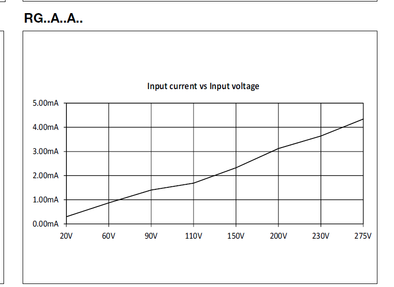
The SRR is the model is RGC3A60A25KK the data sheet is atttachment, you can see the dates in the page 5 the rele for swtiching is 20-275VAC ( but we taste with a power dc, and it change on 13 volts DC it consume 30mA if you give 16 volts it consume 20mA and over 18 volt it consume 10mA).
Regards in advanced
Options
- Mark as New
- Bookmark
- Subscribe
- Mute
- Subscribe to RSS Feed
- Permalink
- Email to a Friend
- Report Inappropriate Content
2024-03-21 10:02 AM
You can take a look at OUT2 with an oscilloscope.
But even if OUT2 reaches the value 18V and some current flows into the SSR, this does not mean that the SSR will trigger. According to its data sheet, a response is guaranteed at 20Vac, from what I calculate 28.3V effective value. It may trigger at 18Vdc, but according to its data sheet this is not guaranteed and has nothing to do with LM324 or LM358.
In my opinion, this SSR is not suitable for being reliably controlled by an LM324/LM358 with 24V VCC. Even an opamp with rail-to-rail output could theoretically only drive with 24V, which is still below the guaranteed response threshold of the SSR (if there is some rectifier bridge inside and my calculation above is correct).
You should first clarify further details about the control of this SSR with its manufacturer so that you know how the control circuit should be designed.
Regards
/Peter
In order to give better visibility on the answered topics, please click on Accept as Solution on the reply which solved your issue or answered your question.
Options
- Mark as New
- Bookmark
- Subscribe
- Mute
- Subscribe to RSS Feed
- Permalink
- Email to a Friend
- Report Inappropriate Content
2024-03-21 10:46 AM
Thank you, tomorrow I will send you two images with the osciloscope, one with LM324 ant the other with the LM358.
Thanks in advanced
Options
- Mark as New
- Bookmark
- Subscribe
- Mute
- Subscribe to RSS Feed
- Permalink
- Email to a Friend
- Report Inappropriate Content
2024-03-22 5:43 AM
Options
- Mark as New
- Bookmark
- Subscribe
- Mute
- Subscribe to RSS Feed
- Permalink
- Email to a Friend
- Report Inappropriate Content
2024-03-22 6:26 AM
As I already wrote, I am quite sure that triggering with such a simple opamp is not a good idea for this particular SSR.
I can't see a stable signal with a clean trigger on your oscilloscope either. After checking your control again, I wonder why you don't simply use an npn transistor or MOSFET to convert PWM with a 5V peak value to control your relais/SSRs? This would also have the advantage that you would have significantly less voltage drop to the SSR. Where do the signals D9 and D10 come from?
Have you tested the SSR directly on a DC source and checked at which voltage value it switches on and off?
In order to give better visibility on the answered topics, please click on Accept as Solution on the reply which solved your issue or answered your question.
Options
- Mark as New
- Bookmark
- Subscribe
- Mute
- Subscribe to RSS Feed
- Permalink
- Email to a Friend
- Report Inappropriate Content
2024-03-22 8:10 AM
Hi Peter.
D9 and D10 come from the chip it give me 0-5 volts in the output to D9, D10.
The D10 is for the Channel 1 for a Belimo valve ( 0-10 volts) and the Channel 2 is for the SRR for this reason I use this chip with 2 channels, I understand for the channel 2 it may be with a Darlington for example ULM2003, but I have a really problem because i dont want change the designe, I hope only change the amplifier operational and solve the problem, similar to LM324 if i can´t I have a big problem.
Respect de SRR direct from a power suply is 14 volts, I attach a Video.
I attach by .rar because .mp4 don´t let me.
Thanks Peter.
Options
- Mark as New
- Bookmark
- Subscribe
- Mute
- Subscribe to RSS Feed
- Permalink
- Email to a Friend
- Report Inappropriate Content
2024-03-22 9:01 AM
The large videos don't help me much because I can't see what the respective result is or should be. In the last video, I can see that you are changing the voltage, but I can't see any associated switching process. I'm not standing next to your setup and therefore don't notice any reaction.
This is exactly what I meant by signal curves: if you can see the PWM signal at IN1+ or IN2+ on channel 1, plus the signal at OUT1 and OUT2 perhaps on channel 2 and, optimally, the output of the SSR, you can draw conclusions from this. However, a video is not necessary, a screenshot with these signals would suffice.
In order to give better visibility on the answered topics, please click on Accept as Solution on the reply which solved your issue or answered your question.
Options
- Mark as New
- Bookmark
- Subscribe
- Mute
- Subscribe to RSS Feed
- Permalink
- Email to a Friend
- Report Inappropriate Content
2024-03-22 12:23 PM
Hi Peter, only for your information.
If I don´t connect the SRR my out2 is perfect, I think may be something in the SRR.
I made a modification like you say me in the board with a NPN, and I solve it, so thanks for all the help that you give me.
Thank you very much, Regards.
Miguel