STM8S SPI: how to use it in 3-wire (bidirectional data) mode?
- Mark as New
- Bookmark
- Subscribe
- Mute
- Subscribe to RSS Feed
- Permalink
- Email to a Friend
- Report Inappropriate Content
2025-01-10 1:46 AM - last edited on 2025-02-08 1:52 AM by Andrew Neil
Hello,
I want to connect STM8S003 & ADXL345 (accelerometer) using SPI 3wire mode (lines ~CS, SCK & MOSI as single bidirectional data line).
According to 'RM0016 Reference manual STM8S...', the register SPI_CR2 of STM8S has BDM (Bidirectional data mode enable) & BDOE bits (Input/Output enable in bidirectional mode).
I expected to use these bits to control SPI 3 wire connection:
SPI_CR2 = <BDM=1 | BDOE=1 | SSI=1 | SSM=1 (Master)> - to set STM8 MOSI as output
SPI_CR2 = <BDM=1 | BDOE=0 | SSI=1 | SSM=1 (Master)> - to set STM8 MOSI as input
To exclude possible questions:
1. ADXL345+ATmega8 was tested in 4wire & 3wire modes, all is OK.
2. ADXL345+STM8S003 in 4wire mode works OK. For 3wire mode I've only disconnected line MISO in hardware.
I also can control SPI_CR2 state, chnging it before SPI operations and write the processess using oscilloscope.
Test:
STM8S transmits 0x80 | 0x2C = 0xAC to ADXL345 then it tries to read the answer.
0x80 - read the state of the Register 0x2C of ADXL345.
Result:
When SPI_CR2 = <BDM=0 | BDOE=0 | SSI=1 | SSM=1 (Master)> (4wire mode), oscilloscope shows correct data transmitting (0xAC). As the MISO line is absent, there is not receiving data (see Osc1.jpg).
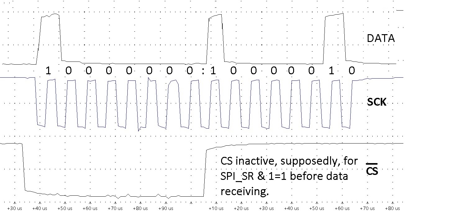
When SPI_CR2 = <BDM=1 | BDOE=1 | SSI=1 | SSM=1 (Master)> (3wire mode), oscilloscope shows incorrect data transmitting: 0x80. (see Osc2.jpg)
Question:
how correctly use BDM & BDOE bits to organize SPI 3wire mode?
or
where one can find an example for SPI 3wire mode?
Examples for SPI 4wire mode are not interesting.
Thanks
#define MISO            7       //all for PORTC
#define MOSI            6
#define SCK             5

//SPI_CR2 bits
#define BDM             7
#define BDOE            6

//SPI_SR bits
#define RXNE            1
#define TXE             2

//~CS pin
#define selectSPI_Device        PC_ODR_bit.ODR4=0
#define unselectSPI_Device      PC_ODR_bit.ODR4=1

void iniSPI()
{
//  CLK_PCKENR1 |=0x02;   //Clock to SPI enabled -in CLK.h
/** SCK preset to 1 **/
  PC_DDR_bit.DDR5 = 1;  //output
  PC_CR1_bit.C15 = 1;   //push-pull for output
  PC_CR2_bit.C25 = 1;   //if output, speed up to 10MHz
//  PC_ODR_bit.ODR5=0;    //SCK=0 - as SPI mode 0 is selected
  PC_ODR_bit.ODR5=1;    //SCK=1 - as SPI mode 0 is selected

/** CS preset to 1 **/
  PC_DDR_bit.DDR4 = 1;  //output
  PC_CR1_bit.C14 = 1;   //push-pull for output
  PC_CR2_bit.C24 = 1;   //if output, speed up to 10MHz
  unselectSPI_Device;  //PC4=1

  SPI_CR1=(1<<6)|(5<<3)|(1<<2)|(1<<1)|(1<<0); //SPI enabled | baudrate F/64 | Master configuration | CPOL=1| CPHA=1
  SPI_CR2=(1<<7)|(1<<6)|(1<<1)|(1<<0);  //1<<7: SPI 3wire (BiDirection mode); 1<<6 MOSI as output; 1<<1: NSS pin is not used for SLAVE-MASTER mode, it is selected by 1<<0: Master mode
}

unsigned char rdSPI(unsigned char d)
{
  while((SPI_SR & RXNE)==0);       //while buffer is empty
  unsigned char res=SPI_DR;
  return(res);
}

void wrSPI(unsigned char d)
{
  SPI_DR = d;
  while((SPI_SR & TXE)==0);       //while buffer is not empty
}

/////////////////////////////

#define D_out SPI_CR2 |=  (1 << BDOE);  //SPI_CR2 |=(1<<6);      //MOSI as Output
#define D_in  SPI_CR2 &= ~(1 << BDOE);  //SPI_CR2 &=~(1<<6);     //MOSI as Input

void DelaySmall()
{
  __no_operation();
  __no_operation();
  __no_operation();
  __no_operation();
}

void iniADXL()
{
//D_out;
  selectSPI_Device;     //FullRes, LeftJust, Range16g(200g)
  wrSPI(0x31);
  wrSPI(0x40 | 0x08 | 0x04 | 0x03);       // SPI 3wire | FullResolution | LeftJustify | Range 16/200g (ADXL345/375)
  unselectSPI_Device;
}

///////////////////////////////
void getRg2C()
{
D_out;
  selectSPI_Device;
  wrSPI(0x2c | 0x80); //Rg0x2C | 0x80 (read state of single Rg 0x2c)
D_in;
  T[0]=rdSPI(0xFF);   //0xE5 -ID of ADXL345 & ADXL375
  unselectSPI_Device;
D_out;
}

//////////////////
void main()
{
//Here UART, TIMERS, CLK, ... are initialized
  iniADXL();
  while(1)
  {
// If UART command is discovered, it'll be exec:
// cmd set STM8S' Rg SPI_SR2 <byte to set>
// cmd getRg2C()
  }
}
Solved! Go to Solution.
Accepted Solutions
- Mark as New
- Bookmark
- Subscribe
- Mute
- Subscribe to RSS Feed
- Permalink
- Email to a Friend
- Report Inappropriate Content
2025-02-08 2:09 AM
AA1, thanks for answer,
but such sequence is not a problem.
Support service proposed solution:
unsigned char rdSPI(unsigned char d)
{
//  while((SPI_SR & RXNE)==0);       //while buffer is empty
    while(SPI_SR_bit.BSY!=0);
This check waits the end of receiving and works correctly.
The previous one stopped the process on the first receiving bit; as it correctly worked in 4-wire mode, I used it in 3-wire mode too.
- Mark as New
- Bookmark
- Subscribe
- Mute
- Subscribe to RSS Feed
- Permalink
- Email to a Friend
- Report Inappropriate Content
2025-02-08 1:49 AM
RM0016 page 273: In this mode, the procedure is similar to the Transmit-only procedure except that the BDM and BDOE bits must both be set in the SPI_CR2 register before enabling the SPI.
But you are setting these bits after enable SPI. Also for SPI mode 0, SCK idle level is 0.
- Mark as New
- Bookmark
- Subscribe
- Mute
- Subscribe to RSS Feed
- Permalink
- Email to a Friend
- Report Inappropriate Content
2025-02-08 2:09 AM
AA1, thanks for answer,
but such sequence is not a problem.
Support service proposed solution:
unsigned char rdSPI(unsigned char d)
{
//  while((SPI_SR & RXNE)==0);       //while buffer is empty
    while(SPI_SR_bit.BSY!=0);
This check waits the end of receiving and works correctly.
The previous one stopped the process on the first receiving bit; as it correctly worked in 4-wire mode, I used it in 3-wire mode too.