Turn on suggestions
Auto-suggest helps you quickly narrow down your search results by suggesting possible matches as you type.
Showing results for
- STMicroelectronics Community
- STM32 MCUs
- STM32 MCUs Embedded software
- x-cube-tcpp in real project
Options
- Subscribe to RSS Feed
- Mark Topic as New
- Mark Topic as Read
- Float this Topic for Current User
- Bookmark
- Subscribe
- Mute
- Printer Friendly Page
x-cube-tcpp in real project
Options
- Mark as New
- Bookmark
- Subscribe
- Mute
- Subscribe to RSS Feed
- Permalink
- Email to a Friend
- Report Inappropriate Content
2024-06-11 4:52 AM
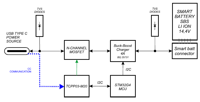
We plan to use STM32G0 mcu with UCPD interface and external TCPP03-M20 protection circuit with single bi-directional power path in our smart power bank with replaceable smart battery and USB-C PD dual role power port application. There will be one USB-C PD connector. And there will be TI BQ25731 Buck-Boost Battery Charge Controller with USB-C PD 3.0 OTG Output that is why we need single bi-directional power path
I have several question if anybody could help me:
1) We plan to offer special non USB-C PD cable which allows to connect directly 12 - 20 V "not power delivery" power supply to USB-C connector. For this scenario, we would like to be able to control single bi-directional power path through TCPP03-M20 mosfet driver directly to enable this non PD power path to connect to battery charger (BQ25731), is it possible to do so?
2) I installed x-cube-tcpp and used NUCLEO-G071RB and X-NUCLEO-DRP1M1 to evaluate the system, I added source and sink PDOs and now I would like to understand, where is the correct place to put BQ25731 setting in case SINK is connected - in terms of BQ25731SetOtgVoltage() and BQ25731SetOtgCurrent() - is it in BSP_USBPD_PWR_VBUSSetVoltage_Fixed function?
I struggle with this a bit because when I request through SINK connected the PDO #2 (9V / 3A) and I put break point in BSP_USBPD_PWR_VBUSSetVoltage_Fixed it seems 5000mV is requested, not 9000mV. I would expect there would be call of this function with 9000mV request.
3) We need to limit charging current depending on maximum power output from SOURCE connected e.g. when 30W PD contract is reached then our maximum charging current is (we use 4 cell Li-Ion smart batteries always) 30W / 16.8V = 1.785A >> 1.5A. Where is the correct and intended place to place this "establish PD contract maximum power readout" in the x-cube-tcpp stack?
thank you
Labels:
- Labels:
-
STM32CubeExpansion
-
USB
1 REPLY 1
Options
- Mark as New
- Bookmark
- Subscribe
- Mute
- Subscribe to RSS Feed
- Permalink
- Email to a Friend
- Report Inappropriate Content
2024-06-21 2:51 AM
Hi @pavelvavra
Interesting application, first, here is an example of two small signal Schottky diodes (D1, D2) to merge the paths while preventing reverse current flow and a 1 MΩ resistor for biasing. Check datasheet for electrical characteristics.

TCPP03-M20 route the power from the power supply to the BQ25731 charger through I2C commands.
To give better visibility on the answered topics, please click on Accept as Solution on the reply which solved your issue or answered your question.
Best regards,
FBL
Related Content
- STM32N6570-DK NonSecure Application not run. in STM32 MCUs Embedded software
- STM32H7 Firmware Update - No Ping in STM32 MCUs Embedded software
- CSConnect Errors When Generating Custom Project in STM32 MCUs Motor control
- In a TouchGFX project, how do I use GPU2D to draw independently? in STM32 MCUs TouchGFX and GUI
- Wakeup from standby with RTC on STM32C5 in STM32 MCUs Embedded software