Turn on suggestions
Auto-suggest helps you quickly narrow down your search results by suggesting possible matches as you type.
Showing results for
- STMicroelectronics Community
- STM32 MCUs
- STM32 MCUs Products
- The stepper/Motor/Driver Pins on the "STM32F407VG-...
Options
- Subscribe to RSS Feed
- Mark Topic as New
- Mark Topic as Read
- Float this Topic for Current User
- Bookmark
- Subscribe
- Mute
- Printer Friendly Page
The stepper/Motor/Driver Pins on the "STM32F407VG-Discover Board & How connect Driver to the Discovery board
Options
- Mark as New
- Bookmark
- Subscribe
- Mute
- Subscribe to RSS Feed
- Permalink
- Email to a Friend
- Report Inappropriate Content
2018-09-03 05:46 PM
Hi all,
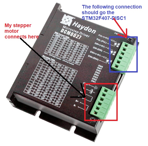
I have been trying to connect a microstep driver (Haydon DCM8027/55 Driver) to the my discover board, but I don't know how to hookup. I have the following board "STM32F407G-Disc1". I am not sure where the stepper motor/driver pins are located on the Discovery board. Any help would be greatly appreciated.
Thanks,
Will
3 REPLIES 3
Options
- Mark as New
- Bookmark
- Subscribe
- Mute
- Subscribe to RSS Feed
- Permalink
- Email to a Friend
- Report Inappropriate Content
2018-09-03 05:58 PM
do you have 5V available ?
Maybe you should try 3.3V first, it should still work and you wont run the risk of destroying the selected Disco pins.
Take 5 or 3.3V to pins
PUL+
DIR+
and ENA+
set the other ends onto the Disco board.
Options
- Mark as New
- Bookmark
- Subscribe
- Mute
- Subscribe to RSS Feed
- Permalink
- Email to a Friend
- Report Inappropriate Content
2018-09-04 10:36 AM
Hi TJ,
Thanks for your reply, I thought I needed to connect PUL+/-/DIR+/ENA+ to the STM32-Discovery board. Am I right? You are saying take 5V/3.3V from the STM32 board and connect them to PUL+/DIR+/ENA+ of the driver, right?
Thanks,
Will
Options
- Mark as New
- Bookmark
- Subscribe
- Mute
- Subscribe to RSS Feed
- Permalink
- Email to a Friend
- Report Inappropriate Content
2018-09-04 05:31 PM
Historically, (1975) DTL was the new technology
Diode / Transistor Logic Best suited to Pull Down Hard...
and we are still using it...
the Pin of your processor can Pull hard Up or Pull Down these days ( 25mA usually)
but your other issue is the requirement of 5V on the LED drive.
You wont be getting 5V from your processor pin, so you cannot drive the LED at 5V
but you can pull low.
some pins are 5V tollerant and you should try to use them, since you can possibly destroy your part over time by over volting..
Luckily for you the LED inside your Motor drive will drop 1 - 2V so the 5V will not be 5V on you pin, but approx 3- 3.7V ( depending on the LED)
but this may be enough leakage to turn on the Motor, so not Ideal.
place a diode in series, to drop a further 0.6V and you will never blow the processor.pin.
Pin- -diode- Pull Down LED pin. 5V on other LED pin.
but of course:
The best method of Voltage translation is through a separate transistor.
Related Content
- STM32F3 discovery board Serial Wire debug not working in STM32 MCUs Products
- Failed to connect USB in CDC Mode for STM32H7474 Discovery Board in STM32 MCUs Products
- NUCLEO-H7S3L8 in STM32 MCUs Products
- Starting PROFINET Stack Development on STM32 in STM32 MCUs Boards and hardware tools
- Writing to flash memory on stm32f746 discovery in STM32 MCUs Embedded software