Turn on suggestions
Auto-suggest helps you quickly narrow down your search results by suggesting possible matches as you type.
Showing results for
- STMicroelectronics Community
- STM32 MCUs
- STM32 MCUs Products
- How to chose resistors value and how to connect th...
Options
- Subscribe to RSS Feed
- Mark Topic as New
- Mark Topic as Read
- Float this Topic for Current User
- Bookmark
- Subscribe
- Mute
- Printer Friendly Page
How to chose resistors value and how to connect them for smt32F2 ADC input pin protection according to technical documentation suggestions?
Options
- Mark as New
- Bookmark
- Subscribe
- Mute
- Subscribe to RSS Feed
- Permalink
- Email to a Friend
- Report Inappropriate Content
2022-08-23 5:21 AM
I was reading related to stm32F07 devices application notes and datasheets for ADC input suggestions.
- AN4899 rev 2 (pg 22)
- DS6329 rev18 (pg 101)
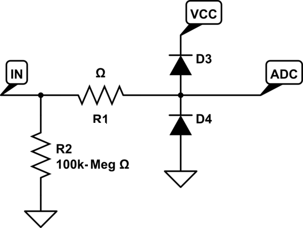
In order to prevent negative and positive current injection, they say:
It is recommended to add a Schottky diode (pin to ground) to analog pins which may potentially inject negative currents.
It is recommended to clamp the input voltage with an external clamp (for instance a series of resistors and the Schottky diode to VREF+).
I'm a bit confused about second kind of connection adding:
- Where should I put the resistors?
- How to get the resistors values?
How should I understand the resistors with schottky diode, source pin and ADC input pin connection?
Are they in serie with:
- the diode?
- adc input (after diodes node)
- before the diodes node?
- both?
- ...
Something like this:
1) img 1
2) img 2
3) img 3
4) another one??
Thanks in advance.
Labels:
- Labels:
-
ADC
-
STM32F2 Series
This discussion is locked. Please start a new topic to ask your question.
2 REPLIES 2
Options
- Mark as New
- Bookmark
- Subscribe
- Mute
- Subscribe to RSS Feed
- Permalink
- Email to a Friend
- Report Inappropriate Content
2022-08-23 6:33 AM
Considering that you won't be giving the adc input directly to the outside world, a current limiting resistor in series with the adc input will be sufficient for small overshoots.
For example, with the RC low pass filter I installed at the output of the opamp that I feed with 5V, it also serves to protect the input from over voltages that the opamp can produce.
If you plan to connect directly to the outside world, I prefer the 2nd connection.
Options
- Mark as New
- Bookmark
- Subscribe
- Mute
- Subscribe to RSS Feed
- Permalink
- Email to a Friend
- Report Inappropriate Content
2022-09-05 3:17 AM
Thanks @Muhammed G�ler, two questions;
1.- Regarding this given information:
___________________________
".. a current limiting resistor in series with the adc input will be sufficient for small overshoots."
Are you talking about NO schottky diode connections? I guess you do. Because the risk of getting different rail VCC values would be null. But not when you get the signal from external circuits, such as my case. The risk increase. Isn't it?
2.- My ADC comes from other card
_____________________________
1.- My adc input signal comes from a group of sensors card.
2.- Every sensor is based on a voltage divisor with variable resistor value depending on objects position.

So I will use two opamp device in order to avoid impedances influency:
- One follower configuration opamp is connected between sensor output signal and the divisor voltage resistors circuit.
- The second follower configuration opamp is connected between these resistors and the ADC input.

- Sensor output is connected to the Vin node.
- Microcontroler card can be powered by 12V and 24V. Opamp is sourced by power bank. Whereas microcontroller is powered by a switching regulator (adjustable output to 3.3V).
Should I put schottky diodes and resistors at the adc input?
Thanks for your attention.
Related Content
- STM32WLE5CCU6 LoRaWAN Stack development in STM32 MCUs Wireless
- STM32H7A3LIH6Q — SWD permanently unresponsive after ~20 flash cycles, UART bootloader work in STM32 MCUs Products
- New STM32CubeIDE for Visual Studio Code 3.9.0 released in STM32CubeIDE for Visual Studio Code (MCUs)
- Using ThreadX thread to provide Vsync with TouchGFX in STM32 MCUs TouchGFX and GUI
- NUCLEO-N657X0-Q does not power up after supplying 7V through VIN with CN9 set to VIN in STM32 MCUs Boards and hardware tools