

Question
Ethernet lwip on STM32F407 board with HAL lib.
Posted on June 08, 2016 at 12:25
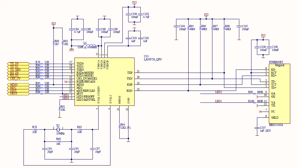 Any tips? Is there anyone who could help me? Anyone who faced the same problem?
Thank you in advance.
Best regards,
�?kos
#cube #discovery #stm32f4 #lwip #dis-bb
Any tips? Is there anyone who could help me? Anyone who faced the same problem?
Thank you in advance.
Best regards,
�?kos
#cube #discovery #stm32f4 #lwip #dis-bb
Hello.
I want to make an UDP communication using mySTM32F407 based board, where the PC forms the server side. I checked most of the posts related to the Ethernet+F407 topic, but could not find any comments that could have lead me in the right direction. The most relevant discussion is this one:/public/STe2ecommunities/mcu/Lists/STM32Discovery/Flat.aspx?RootFolder=https://my.st.com/public/STe2ecommunities/mcu/Lists/STM32Discovery/Ethernet%20configuration%20on%20STM32F407%20Discovery%20board&FolderCTID=0x01200200770978C69A1141439FE559EB459D75800084C20D8867EAD444A5987D47BE638E0F¤tviews=170
, however there the standard peripheral library was finally chosen which solved the problem. In the following i mention all the steps i made. 0)STM32F4xx_Ethernet_Example\udp_echo_client project works fine, i tested using the echotool.exe software provided in theSTM32F4DIS-BB zip package. The problem is that it is based on the SPL, but so far i was working with HAL therefore i would not like to switch back to the old one. 1) i downloaded the latestSTM32Cube package, and tried to modify theSTM324xG_EVAL\LwIP_UDP_Echo_Client project using the parameters applied in theSTM32F4DIS-BB example, these are 2)Project options were changed to 407VGTx, 8Mhz, ST-Link Debugger 3) in the main.h file i modified (IP of the PC: 0.18) a. #define DEST_IP_ADDR3 18 b. #define GW_ADDR3 18 4) in the ethernetif.c file i modified the completeHAL_ETH_MspInit function tovoid HAL_ETH_MspInit(ETH_HandleTypeDef *heth)
{
GPIO_InitTypeDef GPIO_InitStructure;
/* Enable GPIOs clocks */
__HAL_RCC_GPIOA_CLK_ENABLE();
__HAL_RCC_GPIOB_CLK_ENABLE();
__HAL_RCC_GPIOC_CLK_ENABLE();
__HAL_RCC_GPIOD_CLK_ENABLE();
__HAL_RCC_GPIOE_CLK_ENABLE();
/* Enable SYSCFG clock */
__HAL_RCC_SYSCFG_CLK_ENABLE();
/* Ethernet pins configuration ************************************************/
/*
ETH_RMII_REF_CLK-------> PA1 - ok
ETH_MDIO --------------> PA2 - ok
ETH_RMII_CRS_DV -------> PA7 - ok
ETH_MDC ---------------> PC1 - ok
ETH_RMII_RXD0 -------> PC4 - ok
ETH_RMII_RXD1 -------> PC5 - ok
ETH_RMII_TX_EN -------> PB11 - ok
ETH_RMII_TXD0 -------> PB12 - ok
ETH_RMII_TXD1 -------> PB13 - ok
ETH_RST_PIN -------> PE2 - ok
*/
/* Configure PA1, PA2 , PA7 */
GPIO_InitStructure.Pin = GPIO_PIN_1 | GPIO_PIN_2 | GPIO_PIN_7;
GPIO_InitStructure.Speed = GPIO_SPEED_HIGH;
GPIO_InitStructure.Mode = GPIO_MODE_AF_PP;
GPIO_InitStructure.Pull = GPIO_NOPULL;
GPIO_InitStructure.Alternate = GPIO_AF11_ETH;
HAL_GPIO_Init(GPIOA, &GPIO_InitStructure);
/* Configure PB11,PB12 and PB13 */
GPIO_InitStructure.Pin = GPIO_PIN_11 | GPIO_PIN_12 | GPIO_PIN_13;
HAL_GPIO_Init(GPIOB, &GPIO_InitStructure);
/* Configure PC1, PC4 and PC5 */
GPIO_InitStructure.Pin = GPIO_PIN_1 | GPIO_PIN_4 | GPIO_PIN_5;
HAL_GPIO_Init(GPIOC, &GPIO_InitStructure);
/* Configure the PHY RST pin */
GPIO_InitStructure.Pin = GPIO_PIN_2;
GPIO_InitStructure.Mode = GPIO_MODE_OUTPUT_PP;
GPIO_InitStructure.Pull = GPIO_PULLUP;
GPIO_InitStructure.Speed = GPIO_SPEED_FAST;
HAL_GPIO_Init(GPIOE, &GPIO_InitStructure);
HAL_GPIO_WritePin(GPIOE,GPIO_PIN_2, GPIO_PIN_RESET);
HAL_Delay(100);
HAL_GPIO_WritePin(GPIOE,GPIO_PIN_2, GPIO_PIN_SET);
HAL_Delay(100);
/* Enable ETHERNET clock */
__HAL_RCC_ETH_CLK_ENABLE();
}/* ################## Ethernet peripheral configuration ##################### */
/* Section 1 : Ethernet peripheral configuration */
/* MAC ADDRESS: MAC_ADDR0:MAC_ADDR1:MAC_ADDR2:MAC_ADDR3:MAC_ADDR4:MAC_ADDR5 */
#define MAC_ADDR0 2
#define MAC_ADDR1 0
#define MAC_ADDR2 0
#define MAC_ADDR3 0
#define MAC_ADDR4 0
#define MAC_ADDR5 0
/* Definition of the Ethernet driver buffers size and count */
#define ETH_RX_BUF_SIZE ETH_MAX_PACKET_SIZE /* buffer size for receive */
#define ETH_TX_BUF_SIZE ETH_MAX_PACKET_SIZE /* buffer size for transmit */
#define ETH_RXBUFNB ((uint32_t)4) /* 4 Rx buffers of size ETH_RX_BUF_SIZE */
#define ETH_TXBUFNB ((uint32_t)4) /* 4 Tx buffers of size ETH_TX_BUF_SIZE */
/* Section 2: PHY configuration section */
/* DP83848 PHY Address*/
#define DP83848_PHY_ADDRESS 0x01
/* PHY Reset delay these values are based on a 1 ms Systick interrupt*/
#define PHY_RESET_DELAY ((uint32_t)0x000FFFFF)
/* PHY Configuration delay */
#define PHY_CONFIG_DELAY ((uint32_t)0x00FFFFFF)
#define PHY_READ_TO ((uint32_t)0x0000FFFF)
#define PHY_WRITE_TO ((uint32_t)0x0000FFFF)
/* Section 3: Common PHY Registers */
#define PHY_BCR ((uint16_t)0x00) /*!< Transceiver Basic Control Register - ok */
#define PHY_BSR ((uint16_t)0x01) /*!< Transceiver Basic Status Register - ok */
#define PHY_RESET ((uint16_t)0x8000) /*!< PHY Reset - ok */
#define PHY_LOOPBACK ((uint16_t)0x4000) /*!< Select loop-back mode - ok*/
#define PHY_FULLDUPLEX_100M (18)
#define PHY_HALFDUPLEX_100M (8)
#define PHY_FULLDUPLEX_10M (14)
#define PHY_HALFDUPLEX_10M (4)
#define PHY_AUTONEGOTIATION ((uint16_t)0x1000) /*!< Enable auto-negotiation function */
#define PHY_RESTART_AUTONEGOTIATION ((uint16_t)0x0200) /*!< Restart auto-negotiation function */
#define PHY_POWERDOWN ((uint16_t)0x0800) /*!< Select the power down mode */
#define PHY_ISOLATE ((uint16_t)0x0400) /*!< Isolate PHY from MII */
#define PHY_AUTONEGO_COMPLETE ((uint16_t)0x0020) /*!< Auto-Negotiation process completed */
#define PHY_LINKED_STATUS ((uint16_t)0x0004) /*!< Valid link established */
#define PHY_JABBER_DETECTION ((uint16_t)0x0002) /*!< Jabber condition detected */
/* Section 4: Extended PHY Registers */
#define PHY_SR ((uint16_t)31) /* Value for DP83848 PHY */
#define PHY_MICR ((uint16_t)0x11) /*!< MII Interrupt Control Register */
#define PHY_MISR ((uint16_t)0x12) /*!< MII Interrupt Status and Misc. Control Register */
#define PHY_LINK_STATUS ((uint16_t)0x0001) /*!< PHY Link mask */
#define PHY_SPEED_STATUS ((uint16_t)0x0002) /*!< PHY Speed mask */
#define PHY_DUPLEX_STATUS ((uint16_t)0x001C)
#define PHY_MICR_INT_EN ((uint16_t)0x0002) /*!< PHY Enable interrupts */
#define PHY_MICR_INT_OE ((uint16_t)0x0001) /*!< PHY Enable output interrupt events */
#define PHY_MISR_LINK_INT_EN ((uint16_t)0x0020U) /*!< Enable Interrupt on change of link status */
#define PHY_LINK_INTERRUPT ((uint16_t)0x2000U) /*!< PHY link status interrupt mask */int main(void)
{
HAL_Init();
/* Configure the system clock to 168 MHz */
SystemClock_Config();
/* Initialize the LwIP stack */
lwip_init();
/* Configure the Network interface */
Netif_Config();
/* udp client connect */
udp_echoclient_connect();
udp_echoclient_send();
/* Notify user about the network interface config */
User_notification(&gnetif);
/* Infinite loop */
while (1)
{
/* Read a received packet from the Ethernet buffers and send it
to the lwIP for handling */
ethernetif_input(&gnetif);
/* Handle timeouts */
sys_check_timeouts();
}
}