Turn on suggestions
Auto-suggest helps you quickly narrow down your search results by suggesting possible matches as you type.
Showing results for
- STMicroelectronics Community
- Product forums
- ST25 NFC/RFID tags and readers
- ST25RU3993 emits a frequency that differs from the...
Options
- Subscribe to RSS Feed
- Mark Topic as New
- Mark Topic as Read
- Float this Topic for Current User
- Bookmark
- Subscribe
- Mute
- Printer Friendly Page
ST25RU3993 emits a frequency that differs from the requested one by 100kHz. Why could that happen?
Options
- Mark as New
- Bookmark
- Subscribe
- Mute
- Subscribe to RSS Feed
- Permalink
- Email to a Friend
- Report Inappropriate Content
2021-10-24 10:01 AM
We built a system based on application notes and evaluation board schematics and design. It consists of the MCU (stm32f407), RFID reader ST25RU3993, and some RF-related stuff. ST25RU3993 is clocked by an external 20MHz crystal oscillator.
Datasheet for ST25RU3993 says that you can select frequency by selecting reference frequency (25, 50, 100, or 125 kHz) and multipliers *33 and *32 - register A and register B respectively.
So, the final formula for the Frequency is F = Fref * (REG_A*33 + REG_B*32).
Also, they packed in 3 registers, namely PLL MAIN REGISTER 1, 2, 3 (addresses are 17h, 18h, 19h).
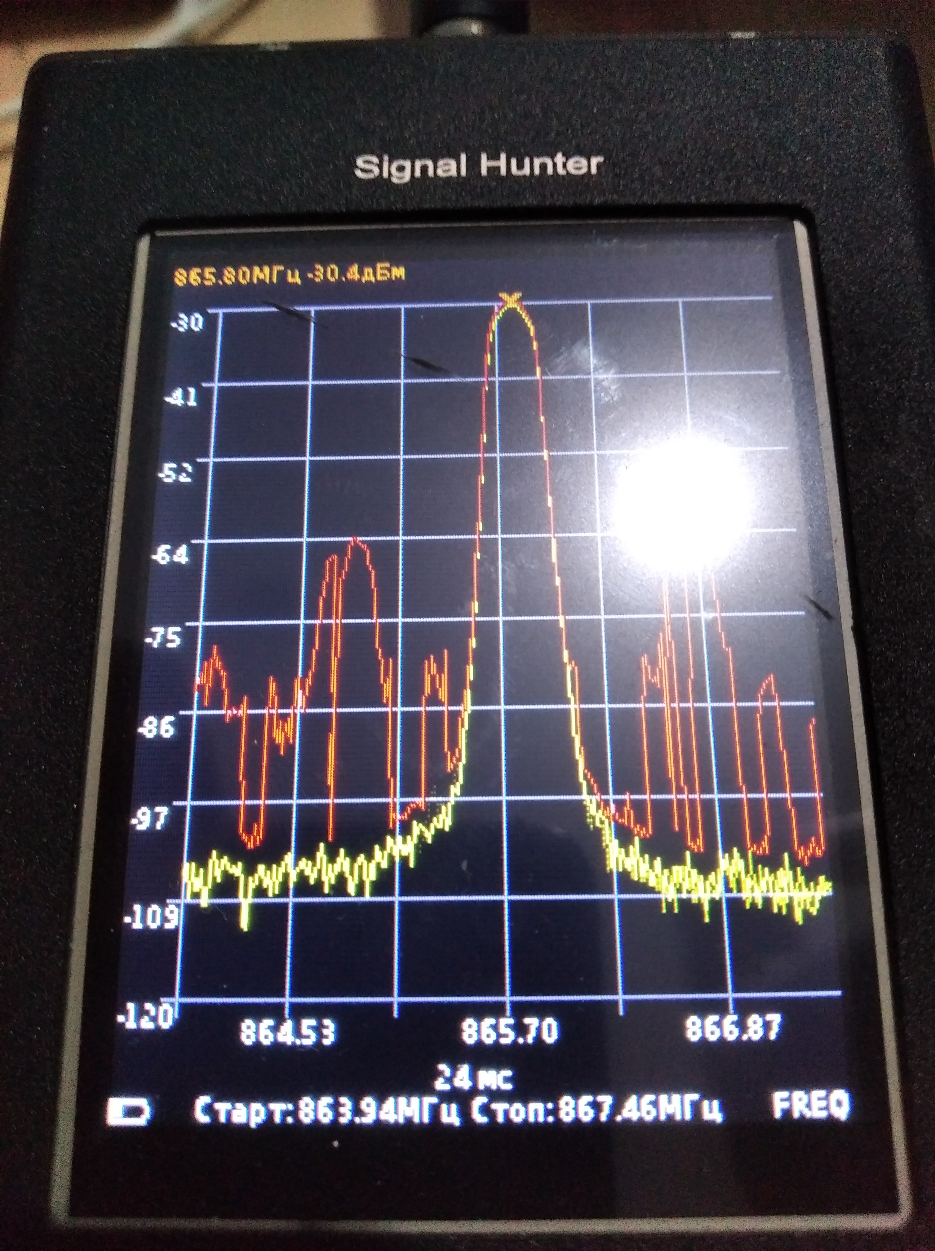
We observe the strange behavior of our system, mentioned in the main question of this message. I used a "signal hunter" device, which is actually an air spectrum analyzer, in order to evaluate, which is actual frequency emitted by the system. And it differs from the requested one. Namely, we requested 865.7 MHz, but the frequency analyzer detects a signal on 865.8 Mhz (see picture: center is on the 865.7MHz, current peek frequency written in yellow at the top of the screen 865.8MHz).
In these cases the following register values were used:
For 25kHz Fref A=548 B=517 regs: 78h 16h 24h
For 50kHz Fref A=258 B=275 regs: 64h 4Dh 02h
For 100kHz Fref A=145 B=121 regs: 51h E4h 91h
I have double-checked the values, written to the registers, and even read them back. Their values look correct. So it looks like the system has some kind of erroneous behavior source in its design.
This behavior does not depend on the reference frequency and has been reproduced with 25,50 and 100 kHz reference frequencies. It also happens at different frequencies: 865.7 MHz, 866.3MHz, 866.9MHz, 867.5MHz.
Any support from ST engineers is greatly appreciated. Can you reproduce such behavior on your side?
Best regards.
Alexander.
Solved! Go to Solution.
Labels:
This discussion is locked. Please start a new topic to ask your question.
1 ACCEPTED SOLUTION
Accepted Solutions
Options
- Mark as New
- Bookmark
- Subscribe
- Mute
- Subscribe to RSS Feed
- Permalink
- Email to a Friend
- Report Inappropriate Content
2021-11-08 2:38 AM
Dear Alexander,
we cannot reproduce the kind of behavior that was described on the evaluation reader ST25RU3993-HPEV.
However, what you may want to check is the frequency of the external 20 MHz crystal oscillator in your design.
It is very likely that the frequency generated is not at 20 MHz.
If this is the case change the lumped load capacitance accordingly.
As an example:
The ST25RU3993-HPEV reader when running with an 20 MHz XTAL (NX3225SA-20.000000MHZ-B2) uses two 11pF capacitors as load capacitors.
With this configuration the carrier frequency is pretty accurate at the desired carrier frequency.
If for an experiment, we are changing the load capacitance values to 8 pF then the carrier frequency shifts already by 30 kHz.
So, I suggest to start by looking at the XTAL frequency in your design.
As an alternative you may consider using and 20 MHz TCXO.
Cheers,
B
1 REPLY 1
Options
- Mark as New
- Bookmark
- Subscribe
- Mute
- Subscribe to RSS Feed
- Permalink
- Email to a Friend
- Report Inappropriate Content
2021-11-08 2:38 AM
Dear Alexander,
we cannot reproduce the kind of behavior that was described on the evaluation reader ST25RU3993-HPEV.
However, what you may want to check is the frequency of the external 20 MHz crystal oscillator in your design.
It is very likely that the frequency generated is not at 20 MHz.
If this is the case change the lumped load capacitance accordingly.
As an example:
The ST25RU3993-HPEV reader when running with an 20 MHz XTAL (NX3225SA-20.000000MHZ-B2) uses two 11pF capacitors as load capacitors.
With this configuration the carrier frequency is pretty accurate at the desired carrier frequency.
If for an experiment, we are changing the load capacitance values to 8 pF then the carrier frequency shifts already by 30 kHz.
So, I suggest to start by looking at the XTAL frequency in your design.
As an alternative you may consider using and 20 MHz TCXO.
Cheers,
B
Related Content
- CMSIS arm_fast_rfft weird results. in STM32 MCUs Embedded software
- Recovering STM32WB05KZ When SWD Is Disabled by BLE Firmware in STM32 MCUs Wireless
- STM32WB05KZ – Cannot Connect After Uploading BLE Beacon Firmware (“Unable to get core ID”) in STM32 MCUs Wireless
- STLINK debugging issue in stop mode (STM32U031C8U6) in STM32 MCUs Products
- Request for Feedback – ST7580-Based Long-Distance FSK over Power Line in Others: hardware and software