Turn on suggestions
Auto-suggest helps you quickly narrow down your search results by suggesting possible matches as you type.
Showing results for
- STMicroelectronics Community
- Product forums
- Power management
- L6470 / L6472 VREG line question
Options
- Subscribe to RSS Feed
- Mark Topic as New
- Mark Topic as Read
- Float this Topic for Current User
- Bookmark
- Subscribe
- Mute
- Printer Friendly Page
L6470 / L6472 VREG line question
Options
- Mark as New
- Bookmark
- Subscribe
- Mute
- Subscribe to RSS Feed
- Permalink
- Email to a Friend
- Report Inappropriate Content
2019-06-07 12:25 PM
Hello,
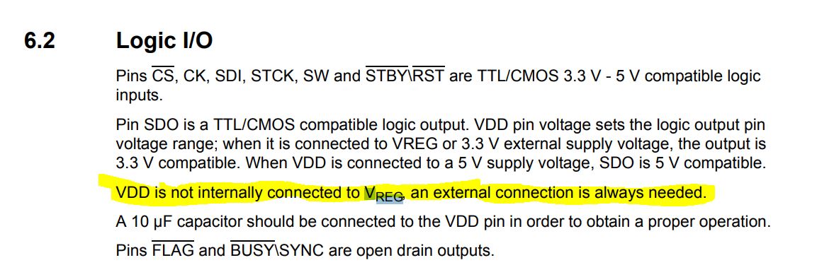
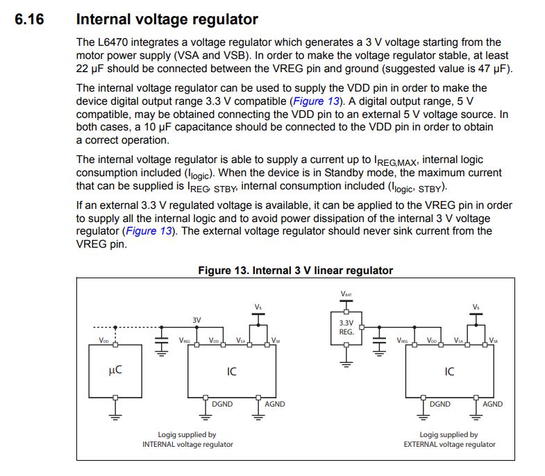
I am designing the system with both L6470PD and L6472PD stepper drivers. Since my system is operating on 3.3V (MCU is STM32F103 ) I have tight the VReg with VDD line as suggested. The problem which I am facing is following. I supply the drivers from 48V while the MCU via DC/DC converter from 24V to 3.3V. If I am turning of the 24V only the logic is still supplied via VREG embedded in Stepper driver ( since 3.3V line is tight with Vreg ). This condition is not good for my application since a) ST not recommended to supply anything from this VREG b) I wanted to be able to turn of the logic completely when I turn on the 24V.
Please advice since it is not clear for me, can I maybe place the Schottky diode between VDD and VReg so there will be no possible supply the system from Vreg?
Or maybe I can leave open the Vreg and not tight this to VDD
Any suggestion is more than great.
Thank you very much
Jacek
Labels:
- Labels:
-
Motor Control Hardware
This discussion is locked. Please start a new topic to ask your question.
13 REPLIES 13
Options
- Mark as New
- Bookmark
- Subscribe
- Mute
- Subscribe to RSS Feed
- Permalink
- Email to a Friend
- Report Inappropriate Content
2019-06-07 3:16 PM
Is it possible you can draw and post a block diagram of the power sources and how you have them connected or wish to have connected ? Not 100% following the setup. You can also submit this as a support request via support home via web request on st.com
Options
- Mark as New
- Bookmark
- Subscribe
- Mute
- Subscribe to RSS Feed
- Permalink
- Email to a Friend
- Report Inappropriate Content
2019-06-07 5:12 PM
Hello Bryan,
Thanks a lot for quick replay.
Here is the block diagram..

Basically I am planning to use 48V to supply the power stage of the H-bridge in L6470 to drive the motors with defined torque. +24V is my main power supply for the rest of electronic system. I am rectify from 24 to 3.3V to supply MCU, Following to spec from L6470 I tight the VREG and VDD to 3.3V line. Now there is a scenario when I unplug the +24V input the MCU is still alive since is sourced from internal VREG from L6470 which is not good in my case ( i need switch off logic completely ). Can I place the Schottky diode in the way that I will be not able to source from VREG the logic , and if yes what I am risking there?
Thank you very much
Jacek
Options
- Mark as New
- Bookmark
- Subscribe
- Mute
- Subscribe to RSS Feed
- Permalink
- Email to a Friend
- Report Inappropriate Content
2019-06-10 12:20 PM
Hi,
Well, I am not an expert on this part, but it appears the :
The Vreg and VDD are indeed supplied externally.. I had to clear that up in my mind.
If you turn off 24volts, it seems all the 3.3 lines will be 0 volts, both the motor driver and MCU.
So I don’t see any need for steering diodes. Sorry, I have not worked with the part before, just reading datasheet, and trying to put myself in your situation.
Best Regards,
Bryan
Options
- Mark as New
- Bookmark
- Subscribe
- Mute
- Subscribe to RSS Feed
- Permalink
- Email to a Friend
- Report Inappropriate Content
2019-06-10 12:30 PM
Hi,
Thanks a lot for replay. Unfortunately is working in this way if I turn off 24V I will have 3.0V on the VDD rail ( not 0V ) from the internal regulator embedded in the L6470PD ( Internal VREG rectify from 48V to 3.0V ) , so my MCU will still respond. So my idea around Schottky diode was to not allow to feed anything from VREG.
Thanks a lot
Jacek Pieczaba
Options
- Mark as New
- Bookmark
- Subscribe
- Mute
- Subscribe to RSS Feed
- Permalink
- Email to a Friend
- Report Inappropriate Content
2019-06-10 12:36 PM
IS this measured ? I did not see the Vreg being powered from the connections from main power ☺
I will look again
I will look again
Options
- Mark as New
- Bookmark
- Subscribe
- Mute
- Subscribe to RSS Feed
- Permalink
- Email to a Friend
- Report Inappropriate Content
2019-06-10 12:37 PM
Ah yes I see it now…
Options
- Mark as New
- Bookmark
- Subscribe
- Mute
- Subscribe to RSS Feed
- Permalink
- Email to a Friend
- Report Inappropriate Content
2019-06-10 12:37 PM
Yes it is measured...
Options
- Mark as New
- Bookmark
- Subscribe
- Mute
- Subscribe to RSS Feed
- Permalink
- Email to a Friend
- Report Inappropriate Content
2019-06-10 12:46 PM
Yes, of course, I did not read enough..! has been a rough morning.
So.. most elegant and simple perhaps, a “switch�? in line with L6470 Vreg, that the truth table is 24v = 1, switch on. 24v = 0 , switch off. So a series FET - so neither 24v supply output or mcu can see l6470 vreg voltage when 24v is off
Does that makes sense to you ?
So.. most elegant and simple perhaps, a “switch�? in line with L6470 Vreg, that the truth table is 24v = 1, switch on. 24v = 0 , switch off. So a series FET - so neither 24v supply output or mcu can see l6470 vreg voltage when 24v is off
Does that makes sense to you ?
Options
- Mark as New
- Bookmark
- Subscribe
- Mute
- Subscribe to RSS Feed
- Permalink
- Email to a Friend
- Report Inappropriate Content
2019-06-10 12:50 PM
But of other concern, is maybe the SPI lines could be “active�? but with no mcu power. I have no clue if that’s ok or not. ;)
Related Content
- L6470 Stepper Driver - Large cap on VS to ground destroyed?? in STM32 MCUs Motor control
- L6470 Different angular speed on stepper motors using RUN command in Power management
- Question about speed profiles for a L6470 in Power management
- L6470 and L6472 - What sets the speed of MOVE and GOTO operations? Using MAX_SPEED parameter imposes lower limit of 15.25 FS/sec and 15.25 FS/sec granularity. in Power management
- Can not set L6470 register in Power management