Get ready for the STM32 Summit 2026 | Online, November 3
Find useful information on analog and audio applications: TDA7294-based designs, PDM to PCM noise, and SPICE models.
Most recent activity
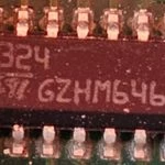
looking to identify this IC, it's most likely from the mid to late 70s and my own hunt has turned up nothing, I would expect it to most likely be some form of amplifier as it is used in a preamp circuit. Any help would be appreciated, thanks!Fergus.
Hi teamI am using TS9222 ( two stage inverting buffer) op-amp as a microphone pre amplifier. it will acts as a voltage follower. Resistor set in the inverting input and feedback is 47K. capacitor in the feedback is 100pF. this is repeating twice(two stage). In the non inverting input it is pulled to vcc/2. My aim is to measure the input and output impedance of this amplifier using bode 100 tool. Please share the impedance analysis procedure if you have( bode 100). Any other method or tool recommended ?. Can i try the same in ST simulation tool?I used impedance analysis simple method also. I tried output impedance analysis method, I am getting distorted output (expecting half time input voltage without any distortion) if the load impedance becomes less than 1.6K for 2.5V+ 1Vpeak( offset+ ac) 1KHz sine wave input. This is not good way to use max power transfer theorem since voltage is clipping below 1.6k. I am getting 15K as the input impedance in the same way.
Hello guys, Newbie here and was wondering if you can help.Was looking for MEMS microphones to enhance predicitive maintenance and cam across the IMP23BSU and seems like it is pretty suitable to enhance predictive maintenance. Although, in industrial environment (with lots of noise) is it still suitable to be installed on the outside of an AMR for specific noise detections?Any tips of other microphones that can be used?Thank you
Hello,can we connect the exposed pad of the TSB582IDT to GND in the PCB layout?There is nothing mentioned in the datasheet regarding the exposed pad.
Dear all,I am using STW81200 as a PLL LO signal generator. I have designed my own PCB strictly following the reccomendations and reference design of evaluation kit. Currently I am trying to perform SPI communication between host FPGA and my PLL circuit, but I am having some problems receiving any return signal on MISO SPI line. I am performing a read operation trying to receive the chip ID stated as in the datasheet but I am receiving nothing. I have soldered two different chips and both behave the same so I elimited the risk of poor soldering. I have attached also STM32l152c board to perform SPI reading but withouth any success so I am eliminating the risk of FPGA code and configuration problem. Each PLL consumes approximately 50 mA. I measured power supply pins voltage and I get 5V and 2.5V on correct pins. As both circuits behave in simillair way I have a feeling that the issue has to do something with my circuit or something that I am missing. I am attaching a schematics bellow and
Please share the CMRT update and remove high risk smelter list CID002547 CID000769 CID001622 CID001916 CID002314
What's the least expensive device that can receive analog audio in, and output I2S audio data?Input resolution should be 16 bits or higher, sample rate 48 kHz or higher. Is there a dedicated ADC chip? or, the STM32G030?
Hi , were can i find data about the LMC7101ILT terminals plating ?
Hey,I'm currently working on upgrading an audio amplifier design I inherited. I've gone through the circuit in detail and I think I've got a handle on most of it. But I'm stumped by the purpose of the highlighted RC circuit. Anybody have any ideas on why it's there? Or maybe could point me in the right direction to figure it out?Cheers,
Hello, I would like to know the distortion of TDA7297 at 40kHz~80kHz. If it's distortion may over 1%, please give some alternatives. Thanks.Reference: https://www.st.com/resource/en/datasheet/tda7297.pdf
Hi All,Could you please advice. Does ADC120 support simultaneous sampling of 8 channels? Can i connect to it 8 IMP23ABSU Analogue MEMS microphones, sample acoustic signals from all microphones for further processing in DSP?
Hello, We have an audio amplifier circuit in our design using the TS482IDT chip. We're wondering if there's any guidance on what is a good value for decoupling capacitors for the chip? Is 0.01uF acceptable? Or Could we use 0.1uF?Thanks,
Hello,I would like to know how to record sound through microphone. I have a STM32L552E-EVAL evaluation board and I have a example provided with this card 'Demo' but after reading the recommendations I still cannot record sound via the headphones provided in this kit. If you have this evaluation card, have you managed to make this card work? I contacted ST but it's been a month and I haven't had any response from them.Thank you for your helps.Regards.
..
Hi everybody,We are using TSX712 in a Sallen-key topology used as low-pass filter We haveC1, C2 = 1 uFR1,R2 = 1KVpsupp = 5VVin = sinusoidal signal with amplitude 4,5 Vpp, offset=2,5V, Freq = 60 HzVout is the expected one when using Capacitors package 0603inch rating-voltage = 50V ;using other kind of Capacitors (0201inch with rating-voltage 6,3 V or 0402inch with rating-voltage = 16 V)Vout has a distorsion in terms of an increasing gradient during increasing amplitude half-period and a decreasing gradient during decreasing amplitude half-period. So Vout sinusoidal time-offset to Vin is not constant (time-offset is decreasing during amplitude-increasing-half-period ; time-offset is increasing during amplitude-decreasing-half-period).Vin maximum value is occurring every half period (at about 8,3 msec)Vout maximum value is occurring before the half period (at about 7,4 msec)This different behaviour, related to used capacitors, is expected ? There are some restrictions
The original TDA7563BDD is replaced by TDA7563BPD. What is the upgrade after the upgrade? Please explain in detail. Thanks. Maybe we can replace the chip with a better one. Any recommendations? Not afraid of expensive. Just as long as it's good.
To whom it may concern, I have an IC, two diiferent IC's in fact, in my hand and it was hard to figure out what they are, their function, or any tech info. I would kindly like to ask for tech feedback, instruction, ie any information you can provide. Photos attached for your convenience. Many thanks, Dragoslav.
Hello,I found this link on the internet : https://github.com/logical/sgtl5000-stm42f4But when i download and try to open it under STM32CubeIDE, I encounter errors such as this window.Do you know how to convert to a correct format under STM32CubeIDE ? Thank you for your advice. Regards.
Dear sir,madam, I have a questions about schematics in figure 3 of TDA7498s datasheet:- should pin PGND (18) be left unconnected to ground?- pin VSS (36) is also left unconnected to ground or it is on potential (VCC - 3.3 V)?- are SUB_GND(1) and for example SGND(27) on the same potential (different symbol)?- can be pin VDDS (26) used instead of external 3.3 V regulator (IC2)?- what is the bias voltage on pins INPA, INNA, INPB and INNB? Is this common voltage available on any pin (maybe SVR (29))?
Hi there,I have a signal which is in the range +600mV. I want to read this using the internal ADC on the STM32L475 uC. To do so, I know I have to shift the signal so it is fully above 0V and I want to do this by connecting the internal DAC to the non-inverting input of one of the internal opamps and then the output of said opamp to the ADC. According to this document, section 3.4.3, it's possible to do with the STM32G series but can it be done with the STM32L series? Additionally, if I had more signals (say 3 for example), do the opamps have a multiplexed input to allow this as there are only 2 opamps present. Again, according to that document, the STM32G series has this but I can't see anything about the STM32L series.Thank you in advance for any help!!
what type( ceramic or MLCC) of capacitor we suppose to use In above both circuit C1 & C2 . Now modern MLCC capacitor available with plenty of advantage . we can use MLCC instead of ceramic capacitor in every circuit ? specifically op amp related circuit in sensor signal amplifying circuit .
Hello,I would like to know if there are people who have already configured the SAI PORT to communicate with a CODEC ?I configured like this :But I don't have the clock on the PIN PF7 :The SAI_MCLK_B is the curve in blue. Thank you for your helps.Regards.
HI ,Has anyone tried to use the STWINMAV expansion board with STEVAL-STWINKT1B board with the firmware FP-AI-PREDMNT?I am having difficulties to set up the SAI using the eloom approach.Hope in any tips, hint!ThanksMassimo
Hello,I have a evaluation board ST32L552E-EVAL, and I would like to know how it works the I2C with this component (for example to initialize the component. Do you know where can I find examples of this board with I2C communication ?I can download an example name 'Demo' but I can't see the file '.ioc' about the clock configuration and also the other parameters to understand with this component.Thank you for your helpsRegards
We found that they came from different manuals, but we compared the two manuals and found no differences.Please tell us the difference between parts "FDA801-VYT"and parts "FDA801B-VYT"?
Already have an account? Login
Enter your E-mail address. We'll send you an e-mail with instructions to reset your password.