

Question
STM32 Timer XOR function TI1S bit, clarification
Posted on July 11, 2014 at 22:03 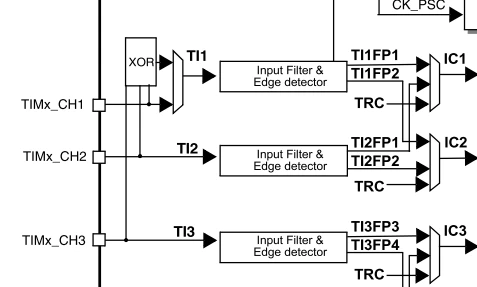 I am refering to the STM32F2xx Ref manual, Timer, XOR function (also known as Hall Sensor Interface) asto above picture-extract on page I try to understand. We have the 3 Timer inputs CH1,2 and 3 each going to its dedicated input-signal-conditioner. On CH1 there is an XOR Gate whos inputs connect to CH1,2 and 3. (Is that a real XOR-Gate or just an OR-Gate??) Its output goes to an ??-Gate that also accepts the original CH1 signal. What Logic Gate would that be?...OR-gate? As i understand, the TI1S-bit would switch the XOR-Gates output to the ??-Gate input. My desired APP was to use CH1 as a clock input. CH2 and CH3 receive a Gate-signal that shall inhibit the CH1 clock when they are high. (XOR function) But it does not seems to work. Has anybody experience with this XOR functionallity?
Bonyour,
I am refering to the STM32F2xx Ref manual, Timer, XOR function (also known as Hall Sensor Interface) asto above picture-extract on page I try to understand. We have the 3 Timer inputs CH1,2 and 3 each going to its dedicated input-signal-conditioner. On CH1 there is an XOR Gate whos inputs connect to CH1,2 and 3. (Is that a real XOR-Gate or just an OR-Gate??) Its output goes to an ??-Gate that also accepts the original CH1 signal. What Logic Gate would that be?...OR-gate? As i understand, the TI1S-bit would switch the XOR-Gates output to the ??-Gate input. My desired APP was to use CH1 as a clock input. CH2 and CH3 receive a Gate-signal that shall inhibit the CH1 clock when they are high. (XOR function) But it does not seems to work. Has anybody experience with this XOR functionallity? 