Turn on suggestions
Auto-suggest helps you quickly narrow down your search results by suggesting possible matches as you type.
Showing results for
- STMicroelectronics Community
- Product forums
- Power management
- Viper06 Buck mode converter, and AN4260
Options
- Subscribe to RSS Feed
- Mark Topic as New
- Mark Topic as Read
- Float this Topic for Current User
- Bookmark
- Subscribe
- Mute
- Printer Friendly Page
Viper06 Buck mode converter, and AN4260
Options
- Mark as New
- Bookmark
- Subscribe
- Mute
- Subscribe to RSS Feed
- Permalink
- Email to a Friend
- Report Inappropriate Content
2024-03-22 12:07 PM
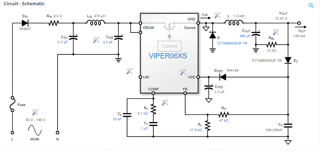
Hello, I need to be able to generate a small DC voltage from an AC voltage.
The App Note 4260 looked absolutely perfect - exactly what I needed - 12V 150mA buck converter. Simple. no flyback transformers, etc. But I was a bit confused as to the GND connection on the IC. It looks like it is connecting to the V-Out instead, with a diode to gnd.
So i went into the edesign suite and used the exact same parameters. the design it shows before you hit "Start design" also shows the diode to gnd on the GND pin, but it also shows another ground symbol. Can you clarify the two different grounds?
The other thing I noticed - it shows a bridge rectifier on the AC input before you tap "start design", but the app note and design you see after you tap "start design" just show the simple single diode rectifier. Can you clarify if I need to add a bridge rectifier on the front? Do I also need the other diode then?
Solved! Go to Solution.
Labels:
- Labels:
-
AC-DC Conversion
This discussion is locked. Please start a new topic to ask your question.
1 ACCEPTED SOLUTION
Accepted Solutions
Options
- Mark as New
- Bookmark
- Subscribe
- Mute
- Subscribe to RSS Feed
- Permalink
- Email to a Friend
- Report Inappropriate Content
2024-03-22 1:18 PM
Well, that's a question of definition: what else is your PCB GND connected to?
If I assume that your PCB GND is connected to the GND with the three dashes and therefore to one pole of the mains voltage in the case of half-wave rectification, then the GND with the triangles must NOT be connected to your PCB GND under ANY circumstances.
You can also remove the triangles and connect their nodes with a wire, then the schematics might be a little easier to understand.
Please keep in mind that the converter is a non-isolating one, i.e. with galvanic connection to the input voltage, usually mains.
Good luck!
Regards
/Peter
In order to give better visibility on the answered topics, please click on Accept as Solution on the reply which solved your issue or answered your question.
3 REPLIES 3
Options
- Mark as New
- Bookmark
- Subscribe
- Mute
- Subscribe to RSS Feed
- Permalink
- Email to a Friend
- Report Inappropriate Content
2024-03-22 12:39 PM
Please do not be confused by the somewhat confusingly drawn GND triangles. They are actually intended to show the flyback regulator, which is "misused" as a classic buck regulator, as a buck. The GND with the small triangles is an internal connection only, NOT to be connected to GND with the three dashes!
The regulated output voltage can then be tapped between VOUT and the GND with the dashes, which is also connected to the negative pole of the input capacitors, for example.
The bridge rectifier is inserted by default because it enables the smallest input ripple current. Of course, the rectifier can then be changed to half-wave rectification with a single rectifier by clicking on it, but using this significantly increases the above-mentioned ripple current and also deteriorates other parameters of the design.
Does it answer your questions?
Regards
/Peter
In order to give better visibility on the answered topics, please click on Accept as Solution on the reply which solved your issue or answered your question.
Options
- Mark as New
- Bookmark
- Subscribe
- Mute
- Subscribe to RSS Feed
- Permalink
- Email to a Friend
- Report Inappropriate Content
2024-03-22 12:55 PM
So none of the triangle grounds are connected to my PCB ground?
Options
- Mark as New
- Bookmark
- Subscribe
- Mute
- Subscribe to RSS Feed
- Permalink
- Email to a Friend
- Report Inappropriate Content
2024-03-22 1:18 PM
Well, that's a question of definition: what else is your PCB GND connected to?
If I assume that your PCB GND is connected to the GND with the three dashes and therefore to one pole of the mains voltage in the case of half-wave rectification, then the GND with the triangles must NOT be connected to your PCB GND under ANY circumstances.
You can also remove the triangles and connect their nodes with a wire, then the schematics might be a little easier to understand.
Please keep in mind that the converter is a non-isolating one, i.e. with galvanic connection to the input voltage, usually mains.
Good luck!
Regards
/Peter
In order to give better visibility on the answered topics, please click on Accept as Solution on the reply which solved your issue or answered your question.
Announcement
We’re moving the ST Community to a new platform to give you a better and more reliable community experience.