STM32G0B1RE + CAN-FD 4 (NCV7344) - CAN FD frames not reaching receiver Raspberry Pi (MCP2517FD)
System Setup
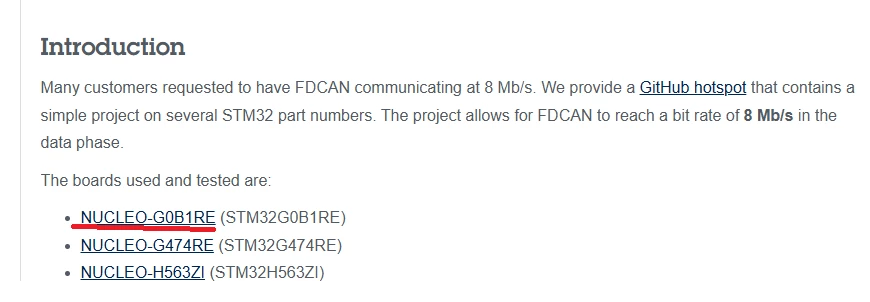
Board: NUCLEO-G0B1RE (STM32G0B1RET6)
CAN Transceiver: CAN-FD 4 Click (NCV7344) connected via level shifter (3.3V → 5V)
FDCAN Pins: PC4 (TX), PC5 (RX) on FDCAN1
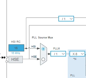
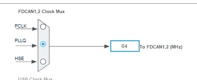
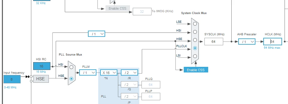
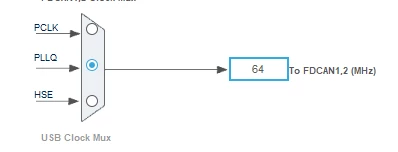
Clock: HSI 16 MHz → PLL → 64 MHz FDCAN clock
Second Node: Raspberry Pi 4 with MCP2517FD Click board (ATA6563 transceiver, 20 MHz crystal)
RPi CAN Interface: can0 configured with bitrate 500000 dbitrate 2000000 fd on
Project Context
I'm building a BMS (Battery Management System) CAN-FD emulator. The STM32 reads values from a potentiometer via ADC and transmits telemetry frames (ID 0x100, 8 bytes) every 100ms. The Raspberry Pi is the receiver that should log these frames.
Problem
When both nodes are connected in FDCAN_MODE_NORMAL, the STM32 transmits frames (confirmed via serial debug prints and g_tx_count incrementing in the debugger), but nothing appears on candump can0 on the Raspberry Pi. The STM32 eventually enters BUS-OFF state.
What I've Already Tested (All Pass)
| STM32 INTERNAL loopback mode | :white_heavy_check_mark:TX = RX, frames received correctly |
| STM32 EXTERNAL loopback mode | :white_heavy_check_mark:TX = RX, transceiver path verified |
| RPi MCP2517FD internal loopback | :white_heavy_check_mark:Frames sent with cansend are received |
| Bus termination resistance (both ends powered off) | :white_heavy_check_mark:60Ω (two 120Ω in parallel) |
| CAN_H / CAN_L idle voltages | :white_heavy_check_mark:~2.5V each |
| NCV7344 STB pin | :white_heavy_check_mark:0V (Normal Mode) |
| ATA6563 STBY pin | :white_heavy_check_mark:0V (Normal Mode) |
| Level shifter output at NCV7344 TXD | :white_heavy_check_mark:4.96V (above VIH min of 3.535V) |
| Level shifter output at NCV7344 RXD | :white_heavy_check_mark:4.96V |
| Continuity CAN_H to CAN_H, CAN_L to CAN_L | :white_heavy_check_mark:Verified |
| Common GND between both systems | :white_heavy_check_mark:Verified |
| RPi ip link show can0 shows | :white_heavy_check_mark: state ERROR-ACTIVE, mtu 72, FD,TDC-AUTO |
STM32 FDCAN Configuration
hfdcan1.Init.FrameFormat = FDCAN_FRAME_FD_BRS;
hfdcan1.Init.Mode = FDCAN_MODE_NORMAL;
hfdcan1.Init.AutoRetransmission = DISABLE;
hfdcan1.Init.NominalPrescaler = 1;
hfdcan1.Init.NominalTimeSeg1 = 101;
hfdcan1.Init.NominalTimeSeg2 = 26;
hfdcan1.Init.DataPrescaler = 1;
hfdcan1.Init.DataTimeSeg1 = 24;
hfdcan1.Init.DataTimeSeg2 = 7;
// TDC Auto mode enabled:
hfdcan1.Instance->DBTP |= FDCAN_DBTP_TDC;
TxHeader Configuration
g_TxHeader.Identifier = 0x100;
g_TxHeader.IdType = FDCAN_STANDARD_ID;
g_TxHeader.TxFrameType = FDCAN_DATA_FRAME;
g_TxHeader.DataLength = FDCAN_DLC_BYTES_8;
g_TxHeader.FDFormat = FDCAN_FD_CAN;
g_TxHeader.BitRateSwitch = FDCAN_BRS_ON;
BUS-OFF Details
When running in NORMAL mode, the STM32's PSR register shows LEC = 5 (Bit Dominant Error), and the node enters BUS-OFF after ~127 failed transmission attempts. The BUS-OFF recovery callback successfully restarts the FDCAN, but frames still don't reach the RPi.
Question
Given that both boards pass internal and external loopback tests, all voltages are correct, termination is verified, and both transceivers are in Normal Mode — what could prevent the NCV7344 from actually driving the CAN bus lines? Is there a known issue with the NCV7344 TxD dominant timeout feature that could lock the transmitter? Any suggestions on what to check next would be greatly appreciated.