
Associate II
February 13, 2024
Question

I CANT RECEİVE ANY MESSAGE FROM A CAN BUS ANALYZER WİTH STM32 BOARD

  • February 13, 2024
  • 32 replies
  • 32057 views

Hello,

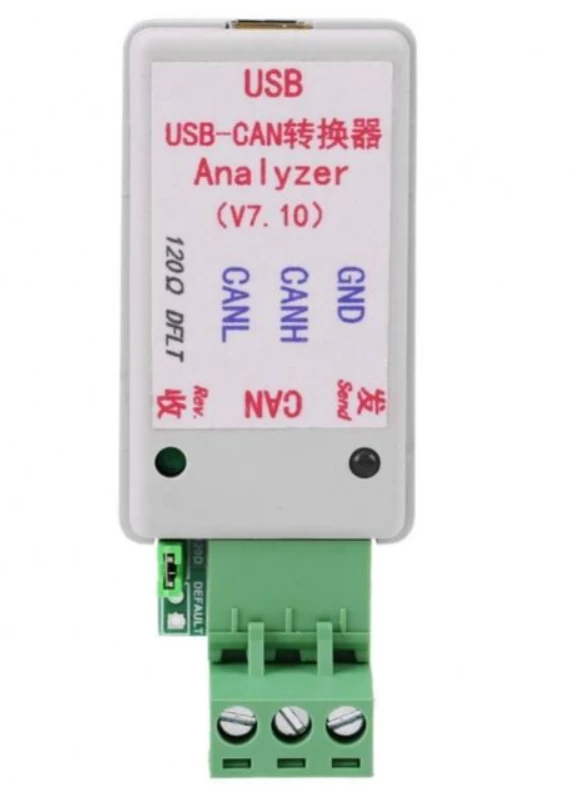
I am using stm32F407VGT board and I am trying to receive data from a can analyzer with stm32 board. I transmit a data to stm32 boards but ı cant receive the messages. I can work on normal mode with two stm32 boards succesfully. The messages are received and transmitted. At the same time, I want to transmit data to can analyzer and I want to observe communication. I attached my main and interrupt source files and I am using USB-CAN analyzerV8 device. The can bps values are the same 500kbps. The modes are same as Normal Mode and I dont define a filter so ı can read every data that ı sent from can analyzer  in live expression on debug screen.

Summarize,

All my purpose, I want to see data that ı sent from can analyzer in my live expression part. I am sending one message fisrtly so there is a one Id.

maZers_1-1707850306830.png


    This topic has been closed for replies.

    32 replies

    Tesla DeLorean
    Guru
    February 13, 2024

    Are you sure on the speed?

    What's your external clock? What's the AHB, APB1 and APB2 bus speeds.

    Are you monitoring the two talking, or just one into the analyzer?

    This looks wrong, but unrelated.

    sFilterConfig.FilterMaskIdHigh=0xFFF0 << 5;

    Tips, Buy me a coffee, or three.. PayPal Venmo (See Profile) Up vote any posts that you find helpful, it shows what's working..
    maZersAuthor
    Associate II
    February 14, 2024

    I am sure that the speeds are the same. It is 500kbps. My external clock is 25Mhz and the Can Bus feeds from the APB1 peripheral. APB1 peripheral is 42Mhz. I want to monitor just stm32. I send a 1 bit data from analayzer and I want to read the data on my stm32 in live expression. Here is a screenshot. You are true about the filter ı forgot the edit filters but yeah unrelated. And I attached a more simple code. The purpose of this program is receiving data from analyzer and observing in live expression. By the way, I am sure that the analyzer is working. Because I received many messages with analyzer from a device that transmit can bus message. and as I said My can bus system is working in normal mode with two stm32 boards

    maZers_0-1707916035529.png


    mƎALLEm
    ST Technical Moderator
    February 14, 2024

    By the way, I am sure that the analyzer is working. Because I received many messages with analyzer from a device that transmit can bus message.

    Ok.. you received messages on the analyzer with another device but did you try its transmit to another device in order to validate that its transmission is working well?

    To give better visibility on the answered topics, please click "Best answer" on the reply which solved your issue or answered your question.
    mƎALLEm
    ST Technical Moderator
    February 14, 2024

    Also, what about termination resistors of 120 ohm?

    To give better visibility on the answered topics, please click "Best answer" on the reply which solved your issue or answered your question.
    maZersAuthor
    Associate II
    February 14, 2024

    I cant observe that the device receive data from analyzer. The device I am talking about just transmit data It doesnt receive data. On the other hand, I can not observe the data that I transmit from stm32 to analyzer. The two board communicate successfully and I want to observe the datas that in Can Bus line with analyzer but I cant observe neither. Should I use an extra HAL function or different an algorithm ? 

    mƎALLEm
    ST Technical Moderator
    February 14, 2024

    @maZers wrote:

    I cant observe that the device receive data from analyzer. The device I am talking about just transmit data It doesnt receive data. On the other hand, I can not observe the data that I transmit from stm32 to analyzer. The two board communicate successfully and I want to observe the datas that in Can Bus line with analyzer but I cant observe neither. Should I use an extra HAL function or different an algorithm ? 


    If the communication between two STM32 boards is OK, I suspect something related to the analyzer. So you need also to validate its transmission. Is it capable to send messages? also check the HW, you need termination resistors  of 120ohm on each side.

    Regarding your implementation in the interrupt:


    void CAN1_RX0_IRQHandler(void)
    {
     /* USER CODE BEGIN CAN1_RX0_IRQn 0 */
    
     /* USER CODE END CAN1_RX0_IRQn 0 */
     HAL_CAN_IRQHandler(&hcan1);
     /* USER CODE BEGIN CAN1_RX0_IRQn 1 */
     for(int i=0; i<pRxHeader.DLC;i++)
     {
    RxData[i];
     }
     HAL_CAN_GetRxMessage(&hcan1,CAN_RX_FIFO0,&pRxHeader,&RxData);
    
     /* USER CODE END CAN1_RX0_IRQn 1 */
    }


    This is not the way we use the HAL.

    You need to use Callbacks such as: HAL_CAN_RxFifo0MsgPendingCallback() and HAL_CAN_RxFifo1MsgPendingCallback()

    To give better visibility on the answered topics, please click "Best answer" on the reply which solved your issue or answered your question.
    maZersAuthor
    Associate II
    February 14, 2024

    By the way, If  my can transciever circuit mcp2551 is wrong, How can I communicate with two stm32 board ? Could you show me an example transciever circuit with MCP2551 ? I will use that  

    maZersAuthor
    Associate II
    February 14, 2024

    I use MCP2551 can transciever IC so I used 60 ohm termination resistor on my stm32 can transciever circuit because In according to MCP2551 datasheet , the termination resistor should be 60 ohm in the recommended connection but There is a 120ohm resistor on the analyzer 

    mƎALLEm
    ST Technical Moderator
    February 14, 2024

    @maZers wrote:

    I use MCP2551 can transciever IC so I used 60 ohm termination resistor on my stm32 can transciever circuit because In according to MCP2551 datasheet  


    Could you please share a screenshot of the part of the MCP2551 datasheet showing that the termination resistor should be at 60 Ohm? I suspect you're are referring to the Test circuit figures ..

    because this is what was said in it:

    SofLit_0-1707919809964.png


    To give better visibility on the answered topics, please click "Best answer" on the reply which solved your issue or answered your question.
    maZersAuthor
    Associate II
    February 14, 2024

    Okey I will follow your tips and get feedback thank you so much 

    maZersAuthor
    Associate II
    February 14, 2024

    Thank you 

    I changed the terminal resistor with 120ohm on my can circuit and It still doesnt work. I cant understand my boards can communicate but why the analyzer can't ? I attached my can transciever circuit . I changed 60 ohm with 120ohm 

    maZers_0-1707929712911.png


    mƎALLEm
    ST Technical Moderator
    February 14, 2024

    It seems you used "Test circuit" description for your project while this is not the right config:

    SofLit_0-1707932476245.png

    So is that possible to:

    1. Remove the following capacitors?:
      • The one connected between CAN_H and CAN_L
      • The one connected to Rx pin
    2. Remove the 2.2Kohm resistor and connect RS pin to the ground
    To give better visibility on the answered topics, please click "Best answer" on the reply which solved your issue or answered your question.
    maZersAuthor
    Associate II
    February 14, 2024

    maZers_0-1707932544448.png

    I tried but it still doesnt work :( I dont know where is the problem. I removed the capacitors except connected +5V one and I connect 120 ohm terminal resistor 

    maZers_1-1707933007194.png

    I attached my code again. I used callback funcitons this time.

    My software purpose's is the received message writed in rcount variable and this data is 1 bit.

    Karl Yamashita
    Principal
    February 14, 2024

    You should check for HAL status when HAL_CAN_Start, HAL_CAN_ActivateNotification and 

    HAL_CAN_ConfigFilter  are called. Make sure they all return HAL_OK. This way we can eliminate an initialization error, if any.


    In the Error_Handler you can turn on an LED to indicate any of those 3 calls did not return HAL_OK.


     if (HAL_CAN_ConfigFilter(&CanHandle, &sFilterConfig) != HAL_OK)
     {
     /* Filter configuration Error */
     Error_Handler();
     }
    
     /*##-3- Start the CAN peripheral ###########################################*/
     if (HAL_CAN_Start(&CanHandle) != HAL_OK)
     {
     /* Start Error */
     Error_Handler();
     }
    
     /*##-4- Activate CAN RX notification #######################################*/
     if (HAL_CAN_ActivateNotification(&CanHandle, CAN_IT_RX_FIFO0_MSG_PENDING) != HAL_OK)
     {
     /* Notification Error */
     Error_Handler();
     }


    If a reply has proven helpful, click on Accept as Solution so that it'll show at top of the post.CAN Jammer an open source CAN bus hacking toolCANableV3 Open Source
    maZersAuthor
    Associate II
    February 14, 2024

    thank you for reply

    I will try this codes but I have a question 

    If I change my can transciever IC MCP2551 with TJA1051,  Can it be better?

    Which can transciever IC do you suggest? 

    maZersAuthor
    Associate II
    February 15, 2024

    Hello again,

    I readjusted my mcp2551 can transciever circuit and my codes. I attached them. But It still doenst work guys. The prgoram is not getting in canrxfifo ınterrupt function or I cant transmit data to analyzer. Maybe, the analyzer sends hex codes not decimal so can I read hex code data in my live expression panel ? I mean, should I decode  the data in my codes ? 

    WhatsApp Image 2024-02-15 at 13.33.14.jpeg