

Associate II
February 13, 2024
Question

I CANT RECEİVE ANY MESSAGE FROM A CAN BUS ANALYZER WİTH STM32 BOARD

Hello,

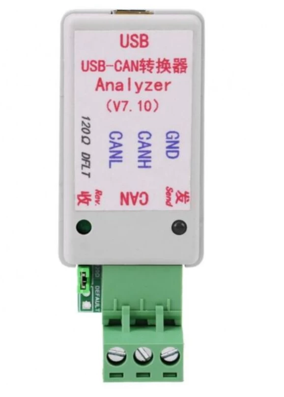
I am using stm32F407VGT board and I am trying to receive data from a can analyzer with stm32 board. I transmit a data to stm32 boards but ı cant receive the messages. I can work on normal mode with two stm32 boards succesfully. The messages are received and transmitted. At the same time, I want to transmit data to can analyzer and I want to observe communication. I attached my main and interrupt source files and I am using USB-CAN analyzerV8 device. The can bps values are the same 500kbps. The modes are same as Normal Mode and I dont define a filter so ı can read every data that ı sent from can analyzer  in live expression on debug screen.

Summarize,

All my purpose, I want to see data that ı sent from can analyzer in my live expression part. I am sending one message fisrtly so there is a one Id.
maZers_1-1707850306830.png


    This topic has been closed for replies.

    32 replies

    Karl Yamashita
    Principal
    February 15, 2024

    Attach your project. Draw up a diagram on how you've connected the MCP2551 to the STM32. How you've connected the CAN analyzer to the MCP2551, including power supply, USB connector(s) and grounds.

    If a reply has proven helpful, click on Accept as Solution so that it'll show at top of the post.CAN Jammer an open source CAN bus hacking toolCANableV3 Open Source
    maZersAuthor
    Associate II
    February 16, 2024

    Here is my projects. I just want to see the received message on the live expression. At the same time, I want to see received message on can analyzer. The communication doesnt work between analyzer and stm32

    WhatsApp Image 2024-02-16 at 12.37.50.jpeg

    Karl Yamashita
    Principal
    February 16, 2024

    Have you checked with an oscilloscope to be sure there is some data activity on the CAN wires?

    If a reply has proven helpful, click on Accept as Solution so that it'll show at top of the post.CAN Jammer an open source CAN bus hacking toolCANableV3 Open Source
    maZersAuthor
    Associate II
    February 16, 2024

    I already used callbacks in my code that I atteched and It doesnt work either. I will use an oscilloscope and check the canbus line signals. In addition, There is no sFilterConfig.FilterMaskIdLow=0x000 yes I forgot it but  does ıt really affect my project ? 

    And If I write the code in Can registers and use ınstances , does the possibility of working project increase ? I mean, I  can start the CAN  with register instead of using HAL lib.

    mƎALLEm
    ST Technical Moderator
    February 20, 2024

    I transmit a data to stm32 boards but ı cant receive the messages. I can work on normal mode with two stm32 boards succesfully. The messages are received and transmitted.

    In your first post you said that the transmission/reception is working fine with two STM32. So I suspect something wrong on CAN Analyzer either with software configuration or HW.

    Do you see any activity on CAN_Rx pin on STM32 side when you send data from the CAN analyzer?


    To give better visibility on the answered topics, please click "Best answer" on the reply which solved your issue or answered your question.
    maZersAuthor
    Associate II
    February 21, 2024

    Hello,

    Here is my schematic

    WhatsApp Image 2024-02-21 at 16.59.50.jpeg

    I observed the can Rx pin with a multimeter. The can Rx pin voltage is 4.88V when no receiving. When I send a message with other stm32 , can rx voltage increase 4.970V and the voltage stay in that value despite I send a data again. Then, I sent a data with analyzer to stm32 , the can rx voltage decreased 2,7V. that is so weird. In addition, when I connect the analyzer in Can Bus line, the stm32 boards doesnt communicate. It breaks the communication.

    My analyzer software settings is right I guess because the can bus kbps is same 500kbps.

    maZers_0-1708524771792.png


    mƎALLEm
    ST Technical Moderator
    February 21, 2024

    We cannot rely on a multimeter for this kind of debug. You need an oscilloscope for this.

    Meanwhile you need to remove one 120ohm on the CAN but.

    You need only two 120 ohm termination resistors at the extremity of the bus. So remove the one of the CAN analyzer.

    To give better visibility on the answered topics, please click "Best answer" on the reply which solved your issue or answered your question.
    maZersAuthor
    Associate II
    February 21, 2024

    I removed the 120ohm on analyzer but it still doesnt work. By the way, when I observe the can bus line with oscilloscope , what should I observe exactly ? How should signals flow on can bus line or Can rx pin ?

    mƎALLEm
    ST Technical Moderator
    February 21, 2024

    When you send data, you have to see the frame on the sender Tx pin and on the receiver Rx pin.

    When the receiver acknowledges the frame, ACK is seen on the receiver Tx pin and also on the sender Rx pin.

    PS: I'm not talking about CAN_H and CAN_L lines.

    To give better visibility on the answered topics, please click "Best answer" on the reply which solved your issue or answered your question.
    maZersAuthor
    Associate II
    February 24, 2024

    Hello, 

    Lets say  I observed the signals with oscilloscope, the ACK's second bit is not 0 dominant so the receiving is failed what will I do ? 

    By the way, according to this schematic before I connect analyzer to stm32 board, the stm32 program works well but when I connect the analyzer to stm32 , an unrelated program is broke like button ınterrupt. I guess, there is a problem on my hardware. You can check out my schema that ı am using and my codes.

    WhatsApp Image 2024-02-16 at 14.51.07.jpeg

    mƎALLEm
    ST Technical Moderator
    February 27, 2024

    By the way, according to this schematic before I connect analyzer to stm32 board, the stm32 program works well but when I connect the analyzer to stm32 , an unrelated program is broke like button ınterrupt. I guess, there is a problem on my hardware.


    From the beginning I suggest you to check this analyzer! It could be an issue from the analyzer. And still having a doubt regarding a possible issue on this HW. As I don't have one to run a test, sorry, I cannot tell you more ..

    Also you need to check the bitrate from the analyzer side, are you sure you set the correct bitrate?

    To give better visibility on the answered topics, please click "Best answer" on the reply which solved your issue or answered your question.
    maZersAuthor
    Associate II
    March 1, 2024

    Hello guys 

    I want thank you all for helping. My problem is solved and I dont know my false :) . I guess this is a bug problem on stm32 cubeıde. I have a few questions about can bus hardware.

    I will use tja1051t/3 as can transciever. Do I have to connect Vıo to 3V ? Is this a essential thing ?.

    The second one, I will use common mode choke for EMI . Is it okey 51uH ? or should I use at least 100uH ınductance in every node ?

    maZers_0-1709304443358.png


    mƎALLEm
    ST Technical Moderator
    March 1, 2024

    Hello,


    I will use tja1051t/3 as can transciever. Do I have to connect Vıo to 3V ? Is this a essential thing ?


    I could answer your first question: indeed you need to connect VIO of the transceiver with the VDD of the MCU to guarantee a good voltage levels between the MCU and the transceiver and exclude the issues related to VIH min when the MCU and the transceiver don't have the same power supply levels. This is why VIO pin is provided on this transceiver's package.

    For the second question you may need to contact the transceiver's manufacturer. 

    To give better visibility on the answered topics, please click "Best answer" on the reply which solved your issue or answered your question.