

My problem: stm32h743 ADC does not convert small signals(about 1-5mv) correctly
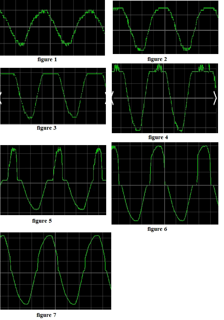
I configure ADC1 and ADC2 in Dual mode, 16 bit resolution, differential-ended. I use CubeMx to initialize ADC. I want measure voltage and current. My project samples the signals and then sends them to the computer for plotting and logging by the WiFi module. When the amplitude of voltage and current are too small, the ADC does not convert the signals correctly. I have attached figures of a logged signal. In these figures the amplitude of voltage changes from 1mV to 9 mV. Figures show that, a part of the signal has not been converted correctly.
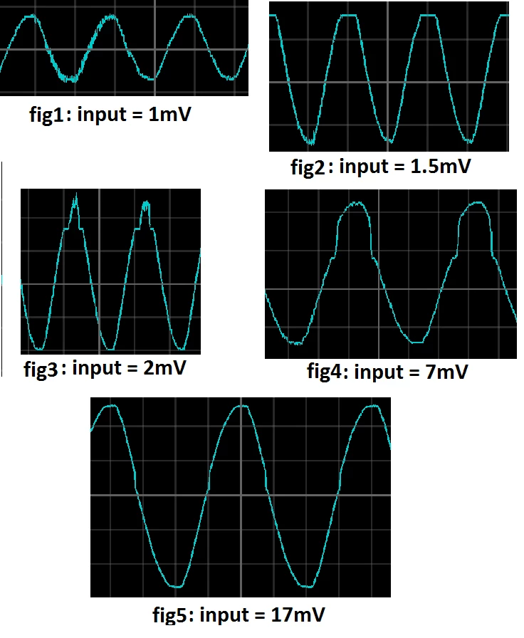
This behaviour is seen in other channel that you can see in below figure.
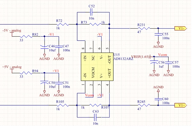
In my hardware, the signal first passes through a differential-ended amplifier (AD8132) and then enters the ADC. The common mode voltage at the amplifier outputs is Vref/2(There is some potential difference (about a few millivolts) between the amplifier outputs). Schematic of the amplifier is attached.
ADCs are initialized by below functions. Sampling frequency is 12KHz.
static void MX_ADC1_Init(void)
{
ADC_MultiModeTypeDef multimode = {0};
ADC_ChannelConfTypeDef sConfig = {0};
hadc1.Instance = ADC1;
hadc1.Init.ClockPrescaler = ADC_CLOCK_ASYNC_DIV6;
hadc1.Init.Resolution = ADC_RESOLUTION_16B;
hadc1.Init.ScanConvMode = ADC_SCAN_ENABLE;
hadc1.Init.EOCSelection = ADC_EOC_SEQ_CONV;
hadc1.Init.LowPowerAutoWait = DISABLE;
hadc1.Init.ContinuousConvMode = DISABLE;
hadc1.Init.NbrOfConversion = 3;
hadc1.Init.DiscontinuousConvMode = DISABLE;
hadc1.Init.ExternalTrigConv = ADC_EXTERNALTRIG_T6_TRGO;
hadc1.Init.ExternalTrigConvEdge = ADC_EXTERNALTRIGCONVEDGE_FALLING;
hadc1.Init.ConversionDataManagement = ADC_CONVERSIONDATA_DMA_CIRCULAR;
hadc1.Init.Overrun = ADC_OVR_DATA_PRESERVED;
hadc1.Init.LeftBitShift = ADC_LEFTBITSHIFT_NONE;
hadc1.Init.OversamplingMode = ENABLE;
hadc1.Init.Oversampling.Ratio = 31;
hadc1.Init.Oversampling.RightBitShift = ADC_RIGHTBITSHIFT_5;
hadc1.Init.Oversampling.TriggeredMode = ADC_TRIGGEREDMODE_SINGLE_TRIGGER;
hadc1.Init.Oversampling.OversamplingStopReset = ADC_REGOVERSAMPLING_CONTINUED_MODE;
if (HAL_ADC_Init(&hadc1) != HAL_OK)
{
Error_Handler();
}
multimode.Mode = ADC_DUALMODE_REGSIMULT_INJECSIMULT;
multimode.DualModeData = ADC_DUALMODEDATAFORMAT_32_10_BITS;
multimode.TwoSamplingDelay = ADC_TWOSAMPLINGDELAY_1CYCLE;
if (HAL_ADCEx_MultiModeConfigChannel(&hadc1, &multimode) != HAL_OK)
{
Error_Handler();
}
sConfig.Channel = ADC_CHANNEL_2;
sConfig.Rank = ADC_REGULAR_RANK_1;
sConfig.SamplingTime = ADC_SAMPLETIME_8CYCLES_5;
sConfig.SingleDiff = ADC_DIFFERENTIAL_ENDED;
sConfig.OffsetNumber = ADC_OFFSET_NONE;
sConfig.Offset = 0;
if (HAL_ADC_ConfigChannel(&hadc1, &sConfig) != HAL_OK)
{
Error_Handler();
}
sConfig.Channel = ADC_CHANNEL_3;
sConfig.Rank = ADC_REGULAR_RANK_2;
if (HAL_ADC_ConfigChannel(&hadc1, &sConfig) != HAL_OK)
{
Error_Handler();
}
sConfig.Channel = ADC_CHANNEL_4;
sConfig.Rank = ADC_REGULAR_RANK_3;
if (HAL_ADC_ConfigChannel(&hadc1, &sConfig) != HAL_OK)
{
Error_Handler();
}
HAL_ADCEx_Calibration_Start(&hadc1, LL_ADC_CALIB_LINEARITY, ADC_DIFFERENTIAL_ENDED);
}
static void MX_ADC2_Init(void)
{
ADC_ChannelConfTypeDef sConfig = {0};
hadc2.Instance = ADC2;
hadc2.Init.ClockPrescaler = ADC_CLOCK_ASYNC_DIV6;
hadc2.Init.Resolution = ADC_RESOLUTION_16B;
hadc2.Init.ScanConvMode = ADC_SCAN_ENABLE;
hadc2.Init.EOCSelection = ADC_EOC_SEQ_CONV;
hadc2.Init.LowPowerAutoWait = DISABLE;
hadc2.Init.ContinuousConvMode = DISABLE;
hadc2.Init.NbrOfConversion = 3;
hadc2.Init.DiscontinuousConvMode = DISABLE;
hadc2.Init.ConversionDataManagement = ADC_CONVERSIONDATA_DMA_CIRCULAR;
hadc2.Init.Overrun = ADC_OVR_DATA_PRESERVED;
hadc2.Init.LeftBitShift = ADC_LEFTBITSHIFT_NONE;
hadc2.Init.OversamplingMode = ENABLE;
hadc2.Init.Oversampling.Ratio = 31;
hadc2.Init.Oversampling.RightBitShift = ADC_RIGHTBITSHIFT_5;
hadc2.Init.Oversampling.TriggeredMode = ADC_TRIGGEREDMODE_SINGLE_TRIGGER;
hadc2.Init.Oversampling.OversamplingStopReset = ADC_REGOVERSAMPLING_CONTINUED_MODE;
if (HAL_ADC_Init(&hadc2) != HAL_OK)
{
Error_Handler();
}
sConfig.Channel = ADC_CHANNEL_18;
sConfig.Rank = ADC_REGULAR_RANK_1;
sConfig.SamplingTime = ADC_SAMPLETIME_8CYCLES_5;
sConfig.SingleDiff = ADC_DIFFERENTIAL_ENDED;
sConfig.OffsetNumber = ADC_OFFSET_NONE;
sConfig.Offset = 0;
if (HAL_ADC_ConfigChannel(&hadc2, &sConfig) != HAL_OK)
{
Error_Handler();
}
sConfig.Channel = ADC_CHANNEL_5;
sConfig.Rank = ADC_REGULAR_RANK_2;
if (HAL_ADC_ConfigChannel(&hadc2, &sConfig) != HAL_OK)
{
Error_Handler();
}
sConfig.Channel = ADC_CHANNEL_2;
sConfig.Rank = ADC_REGULAR_RANK_3;
if (HAL_ADC_ConfigChannel(&hadc2, &sConfig) != HAL_OK)
{
Error_Handler();
}
HAL_ADCEx_Calibration_Start(&hadc2, LL_ADC_CALIB_LINEARITY, ADC_DIFFERENTIAL_ENDED);
}
