Senior
June 20, 2026
Solved

Does the sdmmc1 I/O have internal pull-ups on CMD, D0 D1, D2 and D3?

  • June 20, 2026
  • 17 replies
  • 307 views

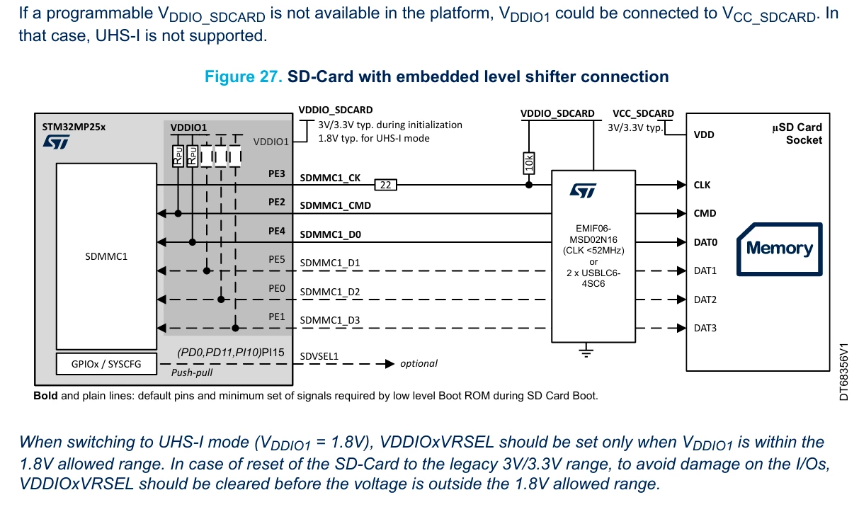
I’m reading the getting started manual of STM32MP257 (AN5489) and it displays that there are internal pull-ups on 

CMD and D0, but not CK.

Also there is a confusion if the dashed lines means they have internal pull-ups as well.

My question is:

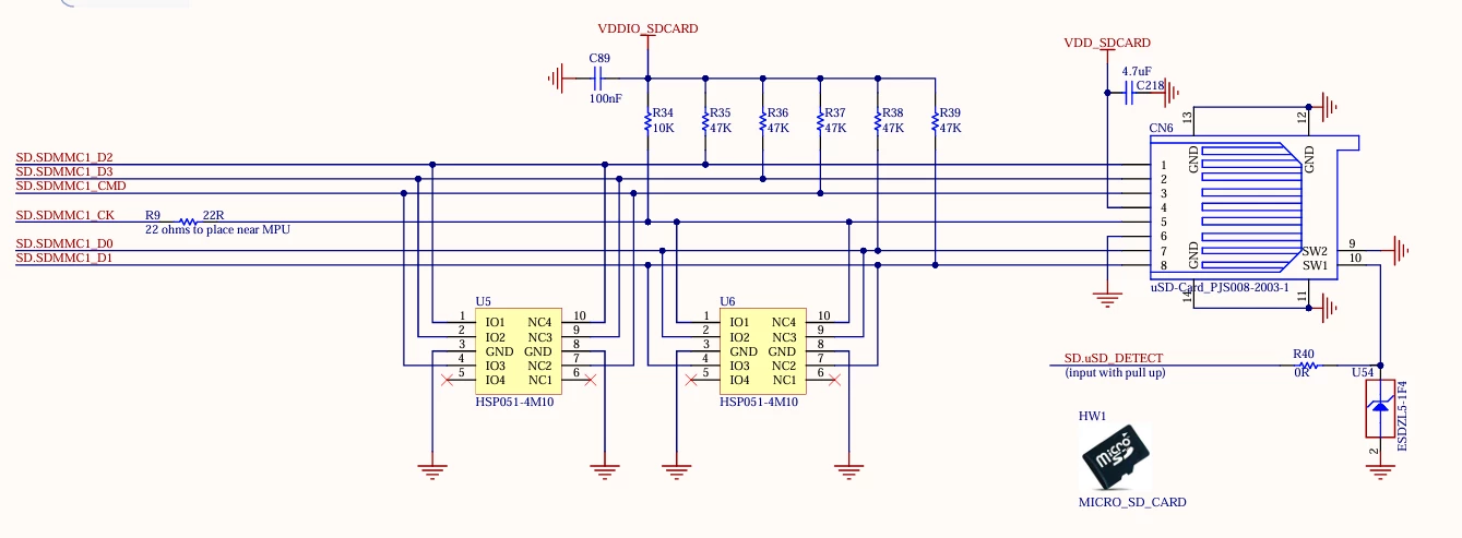
If CMD, D0, D1, D2 and D3 have internal pull-ups. Why does the STM32MP257F-DK board have external pull-ups?

Can I skip these external pull-ups?
 

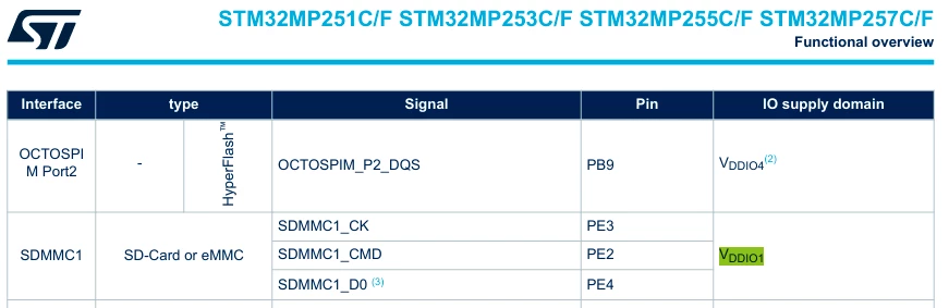
According to the datasheet of STM32MP257C/F (DS14284 - Rev 5), the CK, CMD and D0 MUST be high at initialisation of the BootROM. 

 

Best answer by Windows

Thank you ​@PatrickF  for your reply.

This concludes:

- CLK have a external pull-up just to avoid making it floating before BootROM

- When BootROM loads, then CLK, CMD, D0, D1, D2 and D3 will get their internal pull-ups activated 

- A serie resistor on CLK, near MPU, is good to have only. Even if it's quite unecessary for short traces (less than 30 mm)

- I don't have any vias on my traces (except for the CLK for pull-up

- No external pull-up ups are necessary for CMD, D0, D1, D2 and D3.

- External pull-ups of 10-100 kOhm will not have any impact on signal integrity (except if there is a large T connector for the pull-ups e.g long trace)


So what I will do is that I going to

- Add back the 22 ohm serie resistor for CLK

- Add a 10 kOhm pull-up after the 22 ohm resistor onto the pad (via-in-pad)


What I'm want to inform you is that the getting started manual AN5489 have not correct information at the figure 27. It missing some pull-ups (only blank squares) and the the CLK line is totally missing a pull-up as well.


17 replies

WindowsAuthor
Senior
June 21, 2026

Hi again ​@AScha.3 

I have ask Grok about the pull-ups.

The answer was:

  • No external pull-ups are required of internal pull-ups are available
  • No pull-up on the CLK is requried according to the SD-card standard 3.0 (https://www.farnell.com/datasheets/4159917.pdf)
  • Adding external pull-ups will cause bad signal integrity 

  • If the traces are shorter than 30 mm, then no 22 ohm resistor is needed on the clock for reducing reflections

  • Trace length matching is not required at all for SDR104 and below

  • Keep the EMI-filter close as possible to the SD-card holder

  • If the traces are longer than 30 mm, then add a 22 ohm resistor for the CLK, very close to the processor

  • Keep the traces clean and smooth and a distance from a each other

Let’s do the math about length matching. At the current moment I have this routing: (the blue line is the SD-card detection)


My lengths are:

  • SDMMC1_D2: 8.281 + 1.856 mm = 10.137 mm (-4.033 mm compared to SDMMC1_CK)
  • SDMMC1_D3: 8.182 + 3.354 mm = 11.536 mm (-2.634 mm compared to SDMMC1_CK)
  • SDMMC1_CMD: 7.575 + 4.626 mm = 12.201 mm (-1.969 mm compared to SDMMC1_CK)
  • SDMMC1_CK: 7.181 + 6.989 mm = 14.170 mm (0 mm compared to SDMMC1_CK)
  • SDMMC1_D0: 6.083 + 9.353 mm = 15.436 mm (+1.266 mm compared to SDMMC1_CK)
  • SDMMC1_D1: 6.165 + 10.62 mm = 16.785 mm (+2.615 mm compared to SDMMC1_CK)

So the difference is -4.033 mm to +2.615 mm compared to the clock signal. Is that good or bad? Let’s find out (without using AI)

What do we know to begin with:

  1. The clock frequency for SDR104 is 208 MHz
  2. The period of 208 MHz is 1/(208*10^6)*10^9 = 4.8 ns
  3. The card input setup time (tIS): min 1.4 ns (fCARD = 10pF, VCT= 0.975V)
  4. The card input hold time (tIH): min 0.8 ns (CARD = 5pF, VCT= 0.975V)
  5. Clock rise/fall time: 0.2*4.8 = 0.96 ns

Let’s assume that a microstrip trace that holds 47-55 ohm impedance trace (0.09-0.12 mm) depending on stackup. Let’s assume that this cause a delay of 20 ps for every mm. That’s is a lot because it’s about 14-17 ps/mm in reality, but let’s keep it simple and we round up to 20 ps/mm.

If we assume that the CLK signal of STM32MP257F is the reference, then we get the skew rate with the SDMMC1_CK as the reference

  • SDMMC1_D2: 8.281 + 1.856 mm = 10.137 mm → -80.7 ps  → -0.0807 ns
  • SDMMC1_D3: 8.182 + 3.354 mm = 11.536 mm → -52.7 ps → -0.0527 ns
  • SDMMC1_CMD: 7.575 + 4.626 mm = 12.201 mm → -39.4 ps → -0.0394 ns
  • SDMMC1_CK: 7.181 + 6.989 mm = 14.170 mm → 0 ps → 0 ns
  • SDMMC1_D0: 6.083 + 9.353 mm = 15.436 mm  → +25.3 ps → +0.0253 ns
  • SDMMC1_D1: 6.165 + 10.62 mm = 16.785 mm → +52.3 ps → +0.0523 ns

If we look at the timing table of SDR104 (and also SDR50), we can see that the tIS (time setup) is 1.4 ns and tIH (time hold) is 0.8 ns. My length tuning is in maximum -80 ps to +50 ps compared to the CLK signal. So, as long my signals CMD, D0, D1, D2 and D3 are 1.4 ns faster than the CLK signal and the signals CMD D0, D1, D2 and D3 hold high for about 0.8 ns after the CLK is high, then there is no reason for me to length tuning.

Conclusion:

  • No reason to length tuning an SD-card, even if it’s SDR104. Just route the traces so they smoothly following each other
  • No 22 ohm resistor is required on the CLK signal if the traces are short
  • No pull-up for CLK is requried according to the SD-card standard 3.0
  • Pull-ups (10 kOhm to 100 kOhm) are only requried for CMD, D0, D1, D2 and D3
  • My current routing shows that the signals for my SD card are going arrive at the same time due to the small length difference compared to the CLK signal, even if we are talking about -4.033 mm to +2.615 mm in difference.

So listen to AI...naa….👎🏻

The big question remains for ST Dev Team: Does the STM32MP257F provides pull-ups for SDMMC1?


PatrickF
ST Employee
June 22, 2026

Hi ​@Windows 


That’s great! But unfortunately the EMI-filter EMIF06-MSD02N16 only works for SDR50 SD-cards and below. These days SDR50 is very rareware and difficult to buy because the successor SDR104 is the current standard.

Note that SD card usually (probably always) support lower modes, so any UHS-I SD-Card should work with SDR50 mode.


Regarding pull-up on SDMMC_CLK, it is here to ensure card CLK is not floating during power up and until the BootROM SW has initialized the IOs (from default GPIO analog to SDMMC_CLK output and internal pull-up on SDMMC bidirectional IOs).
Pull-up on clock could be also useful in low power modes to avoid overconsumption if SD-Card supply is not shutdown while IOs are going to high-z.

10K-100k value should work and have no significant signal integrity impact (some minor impact due to T connection to the pull-up resistor if not done carefully).
22 ohms serie is recommended close to the SDMMC_CLK output pin to damp potential output driver and PCB impedance mismatch. Even if not mandatory if all signal integrity analysis are done with care, it allows some signal waveform tuning or measurement (which is not possible later if you put a direct wire).


Regards.

In order to give better visibility on the answered topics, please click on 'Best Answer' on the reply which solved your issue or answered your question.Tip of the day: Try Sidekick STM32 AI agent
WindowsAuthor
Senior
June 22, 2026

Thank you for your reply ​@PatrickF 

And the rest of CMD, D0, D1, D2 and D3 have internal pull-ups as well? I don't need external pull ups on them too?

Understand now why a 10 kOhm pull upp on the clock might be useful now. 

Have ST made some measurements about this statement of 22 ohm serie resistor? I have heard that a serie resistor on CLK line is only needed if the traces are longer than 30 mm.


PatrickF
ST Employee
June 22, 2026

Hi,

Other lines will get internal pullup as well (once intialized, BootROM only make use of CLK, CMD and D0 as first step, then other SW initialize the other data later during boot phases). No mandatory needs of PCB pull-ups.

For SDR104 (max 166MHz 1.8V clock as per datasheet), serie resistor could probably be omitted if traces are really short (30mm is indeed very short) and ~ 55 ohms impedance with very clean traces (few or none vias, etc..).
I cannot give you strong opinion as signal integrity is matter of analysis but sometimes also habits and past experiences.


Regards.


In order to give better visibility on the answered topics, please click on 'Best Answer' on the reply which solved your issue or answered your question.Tip of the day: Try Sidekick STM32 AI agent
WindowsAuthorBest answer
Senior
June 22, 2026

Thank you ​@PatrickF  for your reply.

This concludes:

- CLK have a external pull-up just to avoid making it floating before BootROM

- When BootROM loads, then CLK, CMD, D0, D1, D2 and D3 will get their internal pull-ups activated 

- A serie resistor on CLK, near MPU, is good to have only. Even if it's quite unecessary for short traces (less than 30 mm)

- I don't have any vias on my traces (except for the CLK for pull-up

- No external pull-up ups are necessary for CMD, D0, D1, D2 and D3.

- External pull-ups of 10-100 kOhm will not have any impact on signal integrity (except if there is a large T connector for the pull-ups e.g long trace)


So what I will do is that I going to

- Add back the 22 ohm serie resistor for CLK

- Add a 10 kOhm pull-up after the 22 ohm resistor onto the pad (via-in-pad)


What I'm want to inform you is that the getting started manual AN5489 have not correct information at the figure 27. It missing some pull-ups (only blank squares) and the the CLK line is totally missing a pull-up as well.