Senior
June 20, 2026
Solved

Does the sdmmc1 I/O have internal pull-ups on CMD, D0 D1, D2 and D3?

  • June 20, 2026
  • 17 replies
  • 307 views

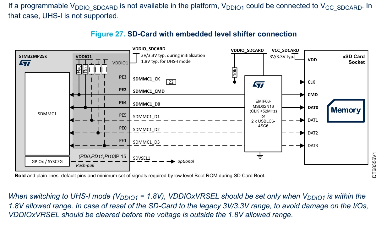
I’m reading the getting started manual of STM32MP257 (AN5489) and it displays that there are internal pull-ups on 

CMD and D0, but not CK.

Also there is a confusion if the dashed lines means they have internal pull-ups as well.

My question is:

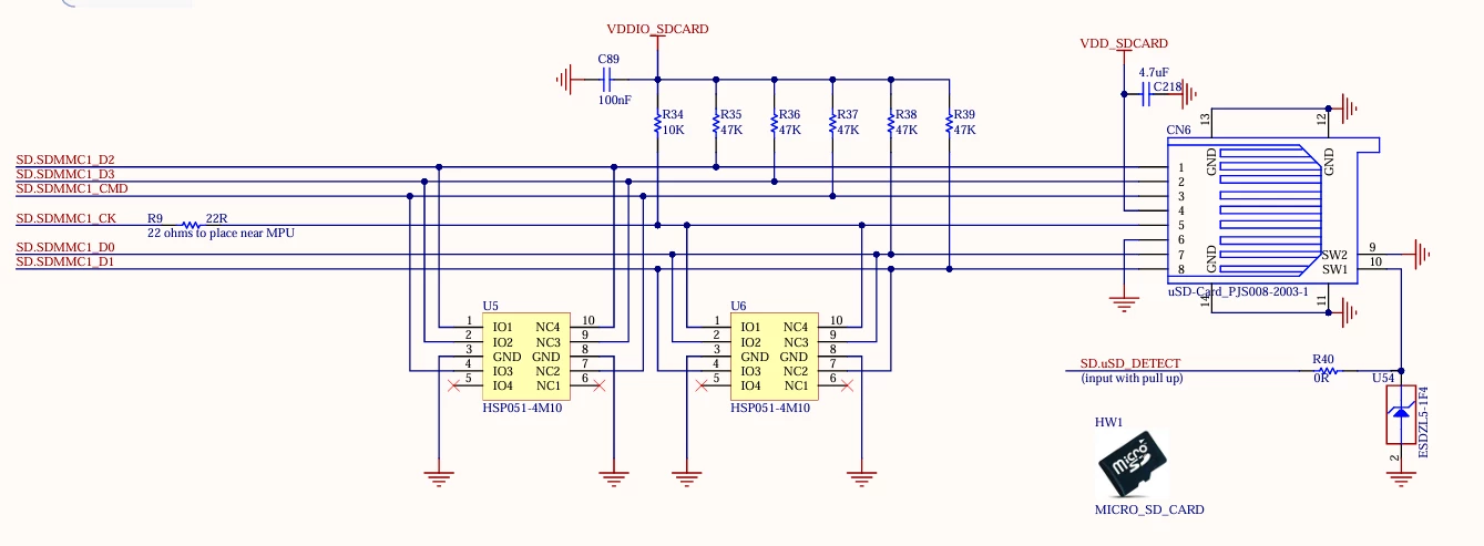
If CMD, D0, D1, D2 and D3 have internal pull-ups. Why does the STM32MP257F-DK board have external pull-ups?

Can I skip these external pull-ups?
 

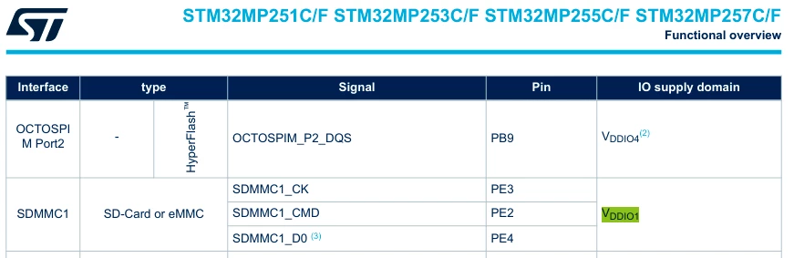
According to the datasheet of STM32MP257C/F (DS14284 - Rev 5), the CK, CMD and D0 MUST be high at initialisation of the BootROM. 

 

Best answer by Windows

Thank you ​@PatrickF  for your reply.

This concludes:

- CLK have a external pull-up just to avoid making it floating before BootROM

- When BootROM loads, then CLK, CMD, D0, D1, D2 and D3 will get their internal pull-ups activated 

- A serie resistor on CLK, near MPU, is good to have only. Even if it's quite unecessary for short traces (less than 30 mm)

- I don't have any vias on my traces (except for the CLK for pull-up

- No external pull-up ups are necessary for CMD, D0, D1, D2 and D3.

- External pull-ups of 10-100 kOhm will not have any impact on signal integrity (except if there is a large T connector for the pull-ups e.g long trace)


So what I will do is that I going to

- Add back the 22 ohm serie resistor for CLK

- Add a 10 kOhm pull-up after the 22 ohm resistor onto the pad (via-in-pad)


What I'm want to inform you is that the getting started manual AN5489 have not correct information at the figure 27. It missing some pull-ups (only blank squares) and the the CLK line is totally missing a pull-up as well.


17 replies

AScha.3
Super User
June 20, 2026

>Can I skip these external pull-ups?

Yes, you can - but i would use them (because hopefully ST knows, what works best with their cpu; and not all are equal !)

  • You could switch on internal pullups, but these are about 40k , so maybe not optimum.
  • Internal pull-up resistors are typically weak (ranging between 30 kΩ and 50 kΩ). The SD Association specifications mandate much stronger pull-ups (typically 10 kΩ) on data/command lines to ensure clean signal integrity, especially at higher clock speeds (e.g., High-Speed or UHS modes). 
  • At initial power-up (before the internal pull-ups are initialized by software), the lines will float, which can lead to erratic behavior or prevent the SD card from being properly detected. 

So saving some cent seems no clever decision here. Just follow the DK board design.

If you feel a post has answered your question, please click on " Best Answer ".
WindowsAuthor
Senior
June 20, 2026

Hi ​@AScha.3 

Thank you so much for the reply!

I know that weak internal pull-ups have a less quality compered to e.g. 0402 external pull-ups.

But! Here is the catch.

At the current moment, I’m using the ST product EMI-filter EMIF06-MSD02N16, which have internal pull-ups. That’s great! But unfortunately the EMI-filter EMIF06-MSD02N16 only works for SDR50 SD-cards and below. These days SDR50 is very rareware and difficult to buy because the successor SDR104 is the current standard.

The only ST product for an EMI-filter that can handle SDR104 is EMIF06-HSD03F3. Unfortunately, the EMI-filter EMIF06-HSD03F3 does not have internal pull-ups as EMIF06-MSD02N16 does.


Answer: You could switch on internal pullups, but these are about 40k , so maybe not optimum.

Reply: Yes! But the internal pull-ups of EMIF06-MSD02N16 is 80 to 100 kOhm, which is more. I have tested the EMIF06-MSD02N16 with STM32MP257F on a custom board. It works if you make sure that the SD-card clock is limited to 50 MHz only. Over that limit, then you will get kernel panic after the linux kernel has been loaded.

Answer: Internal pull-up resistors are typically weak (ranging between 30 kΩ and 50 kΩ). The SD Association specifications mandate much stronger pull-ups (typically 10 kΩ) on data/command lines to ensure clean signal integrity, especially at higher clock speeds (e.g., High-Speed or UHS modes). 

Reply: Do you have a documentation for that? Because most of the EMI-filters for SD-card does not have pull-ups. Having external pull-ups for a high speed signal SDR104 (208 MHz) is very critical and needs to be routed correctly. 

Answer: At initial power-up (before the internal pull-ups are initialized by software), the lines will float, which can lead to erratic behavior or prevent the SD card from being properly detected. 

Reply: Yes, I am aware of that. But I’m not sure that these pull-ups will float, because they are all connected to VDDIO1. I hope any ST Dev Team and explain more about this.

Answer: So saving some cent seems no clever decision here. Just follow the DK board design.

Reply: No, the STM32MP257F-DK board design contains lots of obsolete components and bad components. Also the routing is exepnsive for the purpose. I think ST should update their BOM-list and some components inside the STM32MP257F-DK.

AScha.3
Super User
June 21, 2026

Ok, with “follow the DK board design”  i just meant using pullups...not copy everything.

+

I never had UHS modes, because the H743 etc. dont have native interface for uhs, just 3v3 50Mbit max.;

and i made with and without pullups, then switching on the internal pin pullups , all working fine.

(If short line cpu -- card and pin speed not too high; but here, you, want higher speed, so rules might be different.)

+

what Gemini knows about :

For the STM32MP257C/F: Do not use any external pull-up resistors in the SDR104 high-speed path.


For the STM32MP257C/F: Do not use external pull-up resistors at all in the SDR104 high-speed path. [1]
The STM32MP257 features state-of-the-art I/O cells with programmable internal pull-up stages that are active during the boot and initialization phase (default: 47 kΩ). Once the system switches to 1.8 V for SDR104 mode and clocks up to 208 MHz, the internal controllers drive the data and command lines using a true push-pull configuration. External pull-ups would only degrade signal edge rates in this scenario. [2, 3]
The precise hardware implementation follows the official ST reference designs (e.g., the [STM32MP257F-DK Discovery Kit](https://www.st.com/resource/en/user_manual/um3385-discovery-kit-with-stm32mp257f-mpu-stmicroelectronics.pdf)): [1, 4]
## 1. Power Supply & Level Shifting (Mandatory)
Since the STM32MP257 starts at 3.3 V during boot but must switch down to 1.8 V for SDR104 (signaling voltage switch), a dedicated SD card level shifter is required. ST uses a suitable transceiver on its boards by default.

* No discrete pull-ups: This transceiver (or the STM32's internal I/O ring) handles maintaining the correct signal levels during the high-impedance (tri-state) condition. * Exception regarding the clock line in the ST reference design: On the demo board (STM32MP257F-DK), ST places a weak 10 kΩ pull-up resistor to VDD exclusively on the SDMMC_CK line. This serves solely to prevent clock oscillation during the initial power-up (before the MPU pin actively drives the signal). However, with a clean software boot, this component is often optional. [1]

## 2. Series Termination (Damping Resistors)
Instead of pull-ups, you must include series resistors ($R_s$) to suppress reflections at 208 MHz:

* Place 22 Ω to 33 Ω resistors in each signal line (CLK, CMD, DAT0-3).
* The resistor on the clock line (SDMMC_CK) must be placed as close as possible to the STM32MP257.
* The resistors for the data and command lines (DATx, CMD) should also be placed close to the MPU, as the signals are bidirectional.

## 3. PCB Layout Guidelines (SDR104 on STM32MP2)
Since SDR104 operates in the microwave frequency range, the following rules apply to routing to the MicroSD slot:

* Impedance: All SDMMC interface lines must be routed as 50 Ω single-ended traces over a continuous ground plane (GND plane). Avoid splitting the reference plane.
* Length matching (skew requirement):
* The maximum permissible length difference (mismatch) between all data lines (DAT0–DAT3) and the CMD line is ±0.5 mm. 
* The clock line (CLK) may be at most 1 mm longer or shorter than the data lines. * Reduce vias: Ideally, route the signals entirely on the top layer to avoid vias. If layer transitions are necessary, place a GND stitching via directly next to the signal via.

## Summary for your schematic

1. STM32MP257 → SDMMC pins: No external pull-ups to the data lines.

2. Series connection: 22 Ω resistors in all lines.

3. Software configuration: In the Linux kernel's Device Tree file (.dts), set the pin status for SDR104 to bias-pull-up (for internal pull-ups) for the STM32MP257. The STM32 will then dynamically adjust the timing using its internal tuning algorithm. [1, 3, 5]

Would you like me to find the appropriate device tree extract for the SDMMC interface of the STM32MP257 in SDR104 mode? [5]

[1] [https://community.st.com](https://community.st.com/stm32-mpus-products-and-hardware-related-39/why-10-kohm-pull-up-onto-the-sdmmc1-ck-line-166260)
[2] [https://www.mouser.com](https://www.mouser.com/pdfDocs/um3385-discovery-kit-with-stm32mp257f-mpu-stmicroelectronics.pdf)
[3] [https://www.ac6-training.com](https://www.ac6-training.com/en/cours.php/cat_ST/ref_STR13/stm32u5)
[4] [https://www.st.com](https://www.st.com/resource/en/user_manual/um3385-discovery-kit-with-stm32mp257f-mpu-stmicroelectronics.pdf)
[5] [https://wiki.st.com](https://wiki.st.com/stm32mpu/wiki/SDMMC_device_tree_configuration)


So try equal length, add 22r on all lines (on clk close to cpu) , if possible have pullup resistor at clk ...even if not populated. (Just in case...needed. And on other lines...if no problem with place or stitches - we dont want extra reflections.)

+

Just : why UHS, because all cards working fine on standard speed modes at 3v3 ?

If you feel a post has answered your question, please click on " Best Answer ".
WindowsAuthor
Senior
June 21, 2026

Hi ​@AScha.3 

Thank you.

Ask Gemini about the EMI-filter EMIF06-HSD03F3 i just implemented.


Right now I have: 

- implemented 10 kOhm pull ups on all sdmmc1 lines, including the clock 

- implement the EMI-filter EMIF06-HSD03F3

- 22 ohm resistor for the clock line

- I have not implemented any 22 ohm resistors on other lines of sdmmc1 because that's not how you doing it. The clock line is only what matters.

- Not length matched because I don't have any information about the lengths inside the micro SD card holder and the micro SD card itself

I totally agree that implement external pull-ups resistor will make the signal Integrity worse.

I hope a ST Dev Team member on this forum can explain if it is a need of external pull-up resistors or not.

AScha.3
Super User
June 21, 2026

But you need for uhs speed dampers on all lines !  ...and equal length +/- 0.5mm ! (Length is your copper trace lenght from pin -- to target. )

Otherwise no fun.


→ 2. Series connection: 22 Ω resistors in all lines. !!! at high speed -here- absolutely needed. 


btw i would even try 33 r , your lines seem very short.

+

I had a problem with a 100MHz clock for a fpga: sometimes not working, on many boards.

Found out, it works , when very cold. Hmmm…. line clk --- fpga was just about 10 mm - so what ?

Reflection on 10 mm ?? I just cut and put 51r there - and working fine all the time. Voila.

If you feel a post has answered your question, please click on " Best Answer ".
AScha.3
Super User
June 21, 2026

Gemini...about the filter:

Yes, using the EMIF06-HSD03F3 makes perfect sense for your STM32MP257 design in SDR104 mode.
This component was developed by [STMicroelectronics](https://www.st.com/en/protections-and-emi-filters/emif06-hsd03f3.html) specifically for SD3.0 UHS-I SDR104 (208 MHz). Since a microSD card represents an externally accessible interface, this IC provides highly effective ESD protection for the STM32MP257, filters high-frequency EMI, and saves a significant amount of PCB space. [1, 2, 3]
------------------------------
## Why the IC is suitable for SDR104
Unlike older ESD protection diodes or filters, the EMIF06-HSD03F3 features extremely low line capacitance of only approx. 2.5 pF (C = 2.5 pF). As a result, the high-speed signal at 208 MHz undergoes minimal attenuation, and the edge rate (rise time) of the push-pull driver is preserved—factors that are essential for the STM32MP257's dynamic tuning. [3, 4]
## Key considerations for implementation ## 1. No additional pull-ups or series resistors required [5]

* Integrated structure: The EMIF06-HSD03F3 is an integrated RLC network. It features an extremely low series resistance of just 1 Ω. [4]
* Schematic adjustment: When using this IC, the discrete 22 Ω / 33 Ω series resistors on the data and CMD lines—mentioned in the previous step—are no longer needed. The IC handles both line matching and protection within a single package. [6]

## 2. Placement extremely close to the MicroSD slot

* To maximize ESD protection, the IC must be placed as close as possible to the physical contacts of the MicroSD card holder.
* If an electrostatic discharge occurs (e.g., by touching the card slot), the energy must be immediately diverted to ground via the IC before the pulse can propagate further into the PCB traces and reach the STM32.

## 3. Ground connection (GND routing) is critical

* The IC filters out high-frequency interference by shunting it to ground. According to the [STMicroelectronics datasheet](https://www.st.com/resource/en/datasheet/emif06-hsd03f3.pdf), all GND bumps of the CSP package must be interconnected directly on the PCB. [1, 7, 8]
* Use multiple micro-vias or standard vias directly at the ground pads to connect to the internal ground plane, thereby minimizing the parasitic inductance of the ground path. A poor ground connection completely compromises filter performance and ESD robustness. [7, 8]

## 4. Adhere to strict flow-through routing

* The package (WLCSP flip-chip, 0.4 mm pitch) features an intelligent "flow-through" pinout. This means signals enter on one side and exit on the exact opposite side. [6, 9]
* Avoid sharp bends during routing (use 45° angles instead) and route all 6 lines (CLK, CMD, DAT0-3) in exact parallel through the component to avoid introducing additional propagation delay skew. ## 5. Manufacturing and Package Type (CSP)

* The EMIF06-HSD03F3 comes in a tiny Chip-Scale Package (CSP) measuring just 1.1 mm × 2.4 mm.
* Ensure that your PCB manufacturer can reliably produce structures with a 0.4 mm pitch and that the solder mask (Solder Mask Defined or Non-Solder Mask Defined) is designed exactly according to the ST datasheet specifications for this footprint. [3, 6, 9]

------------------------------
I can assist you with the layout planning. Do you need help with the precise footprint dimensions, or would you like to know the optimal signal pin assignment (CLK, CMD, DAT0-3)? [1] [https://www.st.com](https://www.st.com/resource/en/datasheet/emif06-hsd03f3.pdf)
[2] [https://www.farnell.com](https://www.farnell.com/datasheets/1801178.pdf)
[3] [https://www.st.com](https://www.st.com/en/protections-and-emi-filters/emif06-hsd03f3.html)
[4] [https://www.ersaelectronics.com](https://www.ersaelectronics.com/p/stmicroelectronics-emif06-hsd03f3-5051113)
[5] [https://www.st.com](https://www.st.com/en/protections-and-emi-filters/emi-filters-with-esd-integrated-protection.html)
[6] [https://www.st.com](https://www.st.com/resource/en/datasheet/emif06-hsd03f3.pdf)
[7] [https://www.mouser.com](https://www.mouser.com/datasheet/2/389/emif06_hsd03f3-1849115.pdf)
[8] [https://www.mouser.com](https://www.mouser.com/datasheet/2/389/emif06_hsd03f3-1849115.pdf)
[9] [https://www.st.com](https://www.st.com/resource/en/datasheet/emif06-hsd03f3.pdf)

If you feel a post has answered your question, please click on " Best Answer ".
WindowsAuthor
Senior
June 21, 2026

Hi ​@AScha.3 

Yes I understand. But if you don't know the internal length of the SD card and the SD card holder. Length matching is useless. It's like guessing how long these should be.

When it comes to serial resistors. I have an EMI filter that have 1 ohm resistor in serie with 1 nH coil. Together with 2.5 pF TVS diodes.

Normally, as long the clock line have a delay (e.g resistor of 10-22 ohm) then you don't need to do length matching.


AScha.3
Super User
June 21, 2026

>Length matching is useless. It's like guessing how long these should be.

no. You can assume the designers know, what they do. So all internal lengths equal.

You have to match your lines.

And using the emi filter (if Gemini is right) → no series R needed. The filter should suppress ringing.

If you feel a post has answered your question, please click on " Best Answer ".
WindowsAuthor
Senior
June 21, 2026

Hi ​@AScha.3 

Thank you. And the pull-ups are not needed as well.

I wonder if pull-ups on CLK is necessary?

We are indeed of a need in some information from ST about this.

AScha.3
Super User
June 21, 2026

from…

No, an external 10 kΩ pull-up resistor on the clock line (CLK / SDMMC_CK) is not required for UHS operation (SDR104) of the STM32MP257. On the contrary: a permanent 10 kΩ pull-up on a high-frequency clock line operating at 208 MHz can degrade signal integrity. [1]
However, there is an important distinction between continuous UHS high-speed operation and the BootROM boot phase, which is why STMicroelectronics includes this resistor in some reference designs. [2, 3]
------------------------------
## Why it is detrimental during UHS/SDR104 operation

* Pure push-pull operation: At 208 MHz, the [STM32MP257](https://www.st.com/en/microcontrollers-microprocessors/stm32mp257.html) actively drives the clock using a push-pull stage (active high and active low). The line never enters a high-impedance (tri-state) condition while data is being transmitted. [4, 5]
* Edge distortion: An external 10 kΩ resistor adds parasitic capacitance and an asymmetric load to the line. At 208 MHz, this narrows the "signal eye" (eye diagram) and interferes with the MPU core's dynamic tuning process. This is why dedicated high-speed EMI filters (such as the EMIF06-HSD03F3 you mentioned) explicitly do not feature a pull-up on the clock line. [1, 2, 6]

## Why ST includes it on the STM32MP257F-DK anyway [7]
If you examine the schematic for the official [STM32MP257F-DK Discovery Kit](https://www.st.com/resource/en/user_manual/um3385-discovery-kit-with-stm32mp257f-mpu-stmicroelectronics.pdf), you will indeed find a pull-up resistor on the SDMMC_CK line. The reason for this is purely pragmatic, relating to BootROM initialization: [2]

1. Preventing floating at power-on: Immediately after power-on—and before the BootROM initializes the pin—the GPIO is in a high-impedance state (tri-state). If the line "floats" (oscillates), the SD card might mistakenly interpret this as clock edges and enter an undefined state. [8]
2. BootROM requirement: The STM32MP257's integrated BootROM expects stable logic levels (High) on the lines (CK, CMD, D0) at the start of communication to ensure a clean startup at 400 kHz in standard-speed mode. [3]

## The clean solution for your design
Since you intend to use the EMIF06-HSD03F3, you should keep the signal path for SDR104 as clean as possible:

1. Use the internal MPU pull-ups: The STM32MP257 features internal pull-up resistors on its I/O pins that can be enabled via software. These are activated in the device tree for the boot phase (open-drain or default state) and are automatically disabled—or switched to push-pull mode—once Linux transitions to SDR104 UHS mode (1.8 V). [3, 8]
2. Omitting the external clock pull-up: If your PCB layout is very compact (trace length < 5–7 cm between MPU and card slot) and no significant interference is expected during power-up, omit the external 10 kΩ pull-up on CLK entirely. This ensures optimal signal integrity at 208 MHz. [1, 4, 9]
3. Compromise (option for prototypes): If you require maximum reliability during the boot phase (similar to the ST development board), provide an unpopulated SMD pad (DNP / Do Not Populate) for a 10 kΩ or 47 kΩ resistor connected to the respective I/O voltage. Should timing issues arise during the initial stage of SD card booting—depending on the card type—you can populate this resistor later; ideally, it remains unpopulated during final SDR104 operation. [2]

Would you like assistance with correctly assigning pin states (default, open-drain, sleep) in the STM32MP257 Linux configuration to ensure optimal control of the internal resistors? [8]

[1] [https://community.st.com](https://community.st.com/stm32-mpus-products-and-hardware-related-39/why-10-kohm-pull-up-onto-the-sdmmc1-ck-line-166260)
[2] [https://community.st.com](https://community.st.com/stm32-mpus-products-and-hardware-related-39/why-10-kohm-pull-up-onto-the-sdmmc1-ck-line-166260)
[3] [https://community.st.com](https://community.st.com/stm32-mpus-products-and-hardware-related-39/does-the-sdmmc1-i-o-have-internal-pull-ups-on-cmd-d0-d1-d2-and-d3-166300)
[4] [https://electronics.stackexchange.com](https://electronics.stackexchange.com/questions/598650/sd-card-socket-just-need-to-wire-with-pull-up-resistors)
[5] [https://www.st.com](https://www.st.com/resource/en/user_manual/um3385-discovery-kit-with-stm32mp257f-mpu-stmicroelectronics.pdf)
[6] [https://www.st.com](https://www.st.com/resource/en/user_manual/um3385-discovery-kit-with-stm32mp257f-mpu-stmicroelectronics.pdf)
[7] [https://wiki.st.com](https://wiki.st.com/stm32mpu/wiki/STM32MP25_resources)
[8] [https://wiki.st.com](https://wiki.st.com/stm32mpu/wiki/SDMMC_device_tree_configuration)
[9] [https://community.st.com](https://community.st.com/stm32-mcus-products-25/are-pull-ups-needed-for-sdio-102561)

So i would put the R pullup on clk and leave it open. Just in case its needed for good start, you can put it there and see.

If you feel a post has answered your question, please click on " Best Answer ".
WindowsAuthor
Senior
June 21, 2026

Hi ​@AScha.3 

Thank you for your reply about the Google Gemini promt. 

It will be very interesting to hear from ST Dev Team tomorrow about these pull-ups, including the pull-up for the clock.