

Rob Ashworth
Senior
September 26, 2023
Question

STM32G4 Reset Issue

  • September 26, 2023
  • 24 replies
  • 7700 views

I am having some strange power up (I think) issue with my STM32G431 controller.  Sometimes it runs for a second or two, sometimes nothing.  It will usually not connect via the SWDIO pins so it is difficult to step through in debug to see where the problem is.  I'm suspecting a problem with the clock configuration, SWDIO pins not defaulting to their proper state, or Reset pin problem.  None of which I can put my finger on.  I am used to STM32F4, H7, this is the first time I have used the G4, so willing to accept the problem is on my side!  Any help or pointer appreciated.  I use CubeIDE to configure the clock and generate all of the initialisation code, via the .ioc file. 


void SystemClock_Config(void)
{
 RCC_OscInitTypeDef RCC_OscInitStruct = {0};
 RCC_ClkInitTypeDef RCC_ClkInitStruct = {0};

 /** Configure the main internal regulator output voltage
 */
 HAL_PWREx_ControlVoltageScaling(PWR_REGULATOR_VOLTAGE_SCALE1_BOOST);

 /** Initializes the RCC Oscillators according to the specified parameters
 * in the RCC_OscInitTypeDef structure.
 */
 RCC_OscInitStruct.OscillatorType = RCC_OSCILLATORTYPE_HSE;
 RCC_OscInitStruct.HSEState = RCC_HSE_ON;
 RCC_OscInitStruct.PLL.PLLState = RCC_PLL_ON;
 RCC_OscInitStruct.PLL.PLLSource = RCC_PLLSOURCE_HSE;
 RCC_OscInitStruct.PLL.PLLM = RCC_PLLM_DIV1;
 RCC_OscInitStruct.PLL.PLLN = 40;
 RCC_OscInitStruct.PLL.PLLP = RCC_PLLP_DIV2;
 RCC_OscInitStruct.PLL.PLLQ = RCC_PLLQ_DIV8;
 RCC_OscInitStruct.PLL.PLLR = RCC_PLLR_DIV2;
 if (HAL_RCC_OscConfig(&RCC_OscInitStruct) != HAL_OK)
 {
 Error_Handler();
 }

 /** Initializes the CPU, AHB and APB buses clocks
 */
 RCC_ClkInitStruct.ClockType = RCC_CLOCKTYPE_HCLK|RCC_CLOCKTYPE_SYSCLK
 |RCC_CLOCKTYPE_PCLK1|RCC_CLOCKTYPE_PCLK2;
 RCC_ClkInitStruct.SYSCLKSource = RCC_SYSCLKSOURCE_PLLCLK;
 RCC_ClkInitStruct.AHBCLKDivider = RCC_SYSCLK_DIV1;
 RCC_ClkInitStruct.APB1CLKDivider = RCC_HCLK_DIV1;
 RCC_ClkInitStruct.APB2CLKDivider = RCC_HCLK_DIV1;

 if (HAL_RCC_ClockConfig(&RCC_ClkInitStruct, FLASH_LATENCY_4) != HAL_OK)
 {
 Error_Handler();
 }
 HAL_RCC_MCOConfig(RCC_MCO1, RCC_MCO1SOURCE_HSE, RCC_MCODIV_1);
}
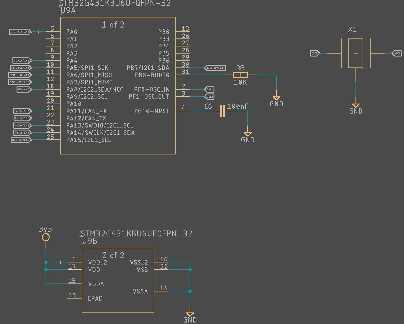

STM32G4 Schematic.jpg

This topic has been closed for replies.

24 replies

TDK
September 28, 2023

> All 4 controllers now cannot be programmed, and 1 is a complete short circuit.

It's not typical for chips to fail even if power is slightly suboptimal. Invalid power is the most likely cause of a fried controller. Could also be from feeding high voltages into GPIO pins, but your circuit seems benign.

Hard to verify the correctness of the EPAD soldering, so we're going to have to take your word there. That's always something to look into.

You never answered the question about bypass and bulk capacitors. Are they present on the board? How exactly is this being powered? What is generating the 3V3?

"If you feel a post has answered your question, please click ""Accept as Solution""."
Rob Ashworth
Senior
September 28, 2023

Here is my PSU from 12V to 3V3.  Admittedly I do not have any 100nF Caps on there, as I tend to find them superfluous. Is that enough to upset thing that I'm seeing the issue Is have?G4 PSU Issue.jpg

TDK
September 28, 2023

> Admittedly I do not have any 100nF Caps on there, as I tend to find them superfluous. Is that enough to upset thing that I'm seeing the issue Is have?

That's what my money is on.

Have you looked at 3V3 during startup on an oscilloscope? Might see a spike that would explain things. No way it's rock solid. A DC-DC converter and no decoupling or bulk caps (beyond 2x22uF) certainly goes against hardware recommendations.

I understand they're inconvenient, but if they weren't necessary, they wouldn't be recommended. You can get away with using less, but probably not none.

TDK_0-1695917745177.png

If you could replace that with an LDO (at least temporarily), might also be worth checking. LDO shouldn't be as prone to spikes.

"If you feel a post has answered your question, please click ""Accept as Solution""."
LCE
Principal II
September 28, 2023

A ceramic resonator, interesting. That really much better than the HSI?
Anyway, with 8 MHz that's seemingly not the problem then.

Rob Ashworth
Senior
September 28, 2023

Ceramic resonator is good for 0.1% clock timing which I need for CANbus.  I usually assume Internal RC clock is only good for 1% for full temperature range, unless anyone else has different experience?

David Littell
Senior II
September 28, 2023

Is your DRDY_ADC at PA0 an EXTI0?  If so, you may be taking that interrupt before your code is ready to handle it (e.g., supporting data structures not yet initialized).  I always go through Core/Src/gpio.c and #if 0 all the HAL_NVIC_EnableIRQ() calls and only do those when I know my code is actually ready/initialized correctly.

Rob Ashworth
Senior
September 28, 2023

Yes it is into EXTI0.  If I get it running again, I will disable everything other than CANbus which I need to see if is failed or not.  I like to fit a Blinky LED, but space is so tight!

LCE
Principal II
September 29, 2023

Unless it breaks the specs of the power source, there cannot be enough capacitors, for stability, noise, EMI, ...

Come on, a controller powering up with 160 MHz, that might be enough to get a supply spike to reset.