
Rob Ashworth
Senior
September 26, 2023
Question

STM32G4 Reset Issue

  • September 26, 2023
  • 24 replies
  • 7700 views

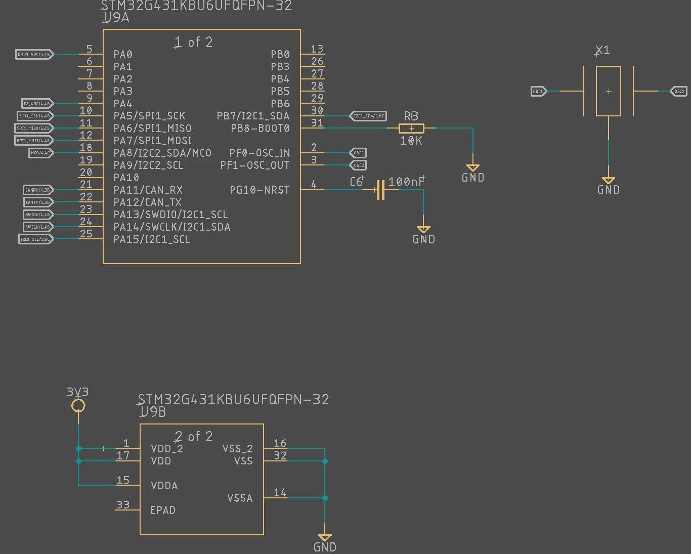
I am having some strange power up (I think) issue with my STM32G431 controller.  Sometimes it runs for a second or two, sometimes nothing.  It will usually not connect via the SWDIO pins so it is difficult to step through in debug to see where the problem is.  I'm suspecting a problem with the clock configuration, SWDIO pins not defaulting to their proper state, or Reset pin problem.  None of which I can put my finger on.  I am used to STM32F4, H7, this is the first time I have used the G4, so willing to accept the problem is on my side!  Any help or pointer appreciated.  I use CubeIDE to configure the clock and generate all of the initialisation code, via the .ioc file. 


void SystemClock_Config(void)
{
 RCC_OscInitTypeDef RCC_OscInitStruct = {0};
 RCC_ClkInitTypeDef RCC_ClkInitStruct = {0};

 /** Configure the main internal regulator output voltage
 */
 HAL_PWREx_ControlVoltageScaling(PWR_REGULATOR_VOLTAGE_SCALE1_BOOST);

 /** Initializes the RCC Oscillators according to the specified parameters
 * in the RCC_OscInitTypeDef structure.
 */
 RCC_OscInitStruct.OscillatorType = RCC_OSCILLATORTYPE_HSE;
 RCC_OscInitStruct.HSEState = RCC_HSE_ON;
 RCC_OscInitStruct.PLL.PLLState = RCC_PLL_ON;
 RCC_OscInitStruct.PLL.PLLSource = RCC_PLLSOURCE_HSE;
 RCC_OscInitStruct.PLL.PLLM = RCC_PLLM_DIV1;
 RCC_OscInitStruct.PLL.PLLN = 40;
 RCC_OscInitStruct.PLL.PLLP = RCC_PLLP_DIV2;
 RCC_OscInitStruct.PLL.PLLQ = RCC_PLLQ_DIV8;
 RCC_OscInitStruct.PLL.PLLR = RCC_PLLR_DIV2;
 if (HAL_RCC_OscConfig(&RCC_OscInitStruct) != HAL_OK)
 {
 Error_Handler();
 }

 /** Initializes the CPU, AHB and APB buses clocks
 */
 RCC_ClkInitStruct.ClockType = RCC_CLOCKTYPE_HCLK|RCC_CLOCKTYPE_SYSCLK
 |RCC_CLOCKTYPE_PCLK1|RCC_CLOCKTYPE_PCLK2;
 RCC_ClkInitStruct.SYSCLKSource = RCC_SYSCLKSOURCE_PLLCLK;
 RCC_ClkInitStruct.AHBCLKDivider = RCC_SYSCLK_DIV1;
 RCC_ClkInitStruct.APB1CLKDivider = RCC_HCLK_DIV1;
 RCC_ClkInitStruct.APB2CLKDivider = RCC_HCLK_DIV1;

 if (HAL_RCC_ClockConfig(&RCC_ClkInitStruct, FLASH_LATENCY_4) != HAL_OK)
 {
 Error_Handler();
 }
 HAL_RCC_MCOConfig(RCC_MCO1, RCC_MCO1SOURCE_HSE, RCC_MCODIV_1);
}

STM32G4 Schematic.jpg

This topic has been closed for replies.

24 replies

Slh
Senior
September 26, 2023

Check if you have a hardware issue. For that you can put a delay for example for 5 second in start of your program. If this delay passed and the problem occurs after delay, then there is no problem in your code and problem can be something else like resetting/hanging microcontroller by switching a loud.


LCE
Principal II
September 26, 2023

No capacitors at X1 ?
Is the G4 special concerning passive crystals, or are the caps somewhere else?
If not, that might be your start-up problem.

To confirm that, switch to HSI for testing.

Rob Ashworth
Senior
September 27, 2023

Thanks, I tried the internal HSI with similar issues, and the crystal is a ceramics resonator with built in caps.


Bubbles
ST Employee
September 26, 2023

Besides of what was already written, I expect the EPAD to be the exposed pad under the package. It's recommended to solder that to PCB ground.

BR,

J

To give better visibility on the answered topics, please click on Accept as Solution on the reply which solved your issue or answered your question.
TDK
September 26, 2023

In addition to missing caps on X1, are there decoupling caps anywhere else? None are shown on your schematic. Each VDD pin needs a 0.1 uF cap, plus a bulk capacitor somewhere on the board.

Guessing the missing EPAD connection is the core issue here.

"If you feel a post has answered your question, please click ""Accept as Solution""."
Rob Ashworth
Senior
September 27, 2023

Thanks for all you suggestions.  For info, the crystal shown is actually a resonator, which includes the caps internally.  I did try the internal HSI, with similar problems, so I don't suspect the crystal.  I do however suspect it could be the EPAD!!  Give me a little while to confirm....

Rob Ashworth
Senior
September 27, 2023

Update, the situation is no better.  I soldered the EPAD, and it made no difference.  I don't get what possible mechanism completely fries the controller.  The PSU is stable 3.3V, monitoring with oscilloscope.  I am on my 4th STM32G now. Is there any machismo that completely frazzles the thing when the PSU looks to be ok?  All 4 controllers now cannot be programmed, and 1 is a complete short circuit.

LCE
Principal II
September 28, 2023

How did you actually connect the EPAD?
I mean, it's a QFN package, and getting the pad soldered that is completely underneath the chip, AND connecting that EPAD to GND is no simple thing, if it wasn't connected to GND from the beginning. 
That screams "solder bridges" somewhere...

For prototyping I prefer LQFP...

Rob Ashworth
Senior
September 28, 2023

Solder to the EPAD retrospectively wasn't easy.  I used a very thin wire to link underneath.  Happy as I could be it was ok, although admittedly I could not X-RAY.  I have used 3 different versions of the PCB attempting to fix the fault, so happy it is also not a Soldering issue, as the fault is always the same.

waclawek.jan
Super User
September 28, 2023

A minimal loopdelay-based blinky (i.e. no clock setup, running from default internal clock) works?

JW

Rob Ashworth
Senior
September 28, 2023

I will try that if I get it going again.  Is it possible the Firmware.My code could kill the IC?  I have not experienced this before, and the only feasible thing I could think of is to perpetually write to the Program memory...I do not believe this happening though as the program would stutter during page writes.

LCE
Principal II
September 28, 2023

I just had a look at your clock settings and compared to an old Nucleo G431 project.

- why PWR_REGULATOR_VOLTAGE_SCALE1_BOOST ?

- your PLL multiplier N = 40 might be too high, assuming your crystal is > 8 MHz, so what's the X1 frequency?

Rob Ashworth
Senior
September 28, 2023

I believe the clock configuration is ok.  I set it up in CubeIDE.  Usually it will have a hissy fit if something is incorrect.

Exact Resonator is a Murate CSTNE8 8 MHz Ceramic Resonator.  I have used it on many other ST devices without issue.

G4 Clock config Issue.jpg

LCE
Principal II
September 28, 2023

And please tell us the exact type of X1.

Rob Ashworth
Senior
September 28, 2023

CSTNE8M00GH5C000