Associate III
October 30, 2023
Solved

STM32 H7 - I2S Clock Timing Problems (runs at 1.027 Mhz for some reason) - See PulseView

  • October 30, 2023
  • 10 replies
  • 7880 views

Hello,

Still trying to get I2S working on the H7...

Opened up PulseView to check the clock between another connected device...

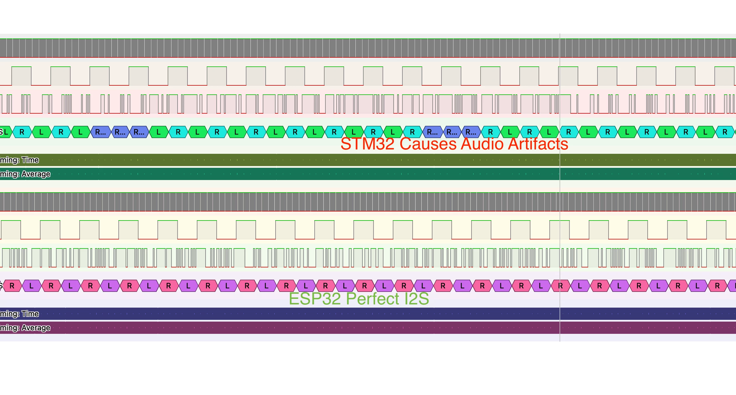
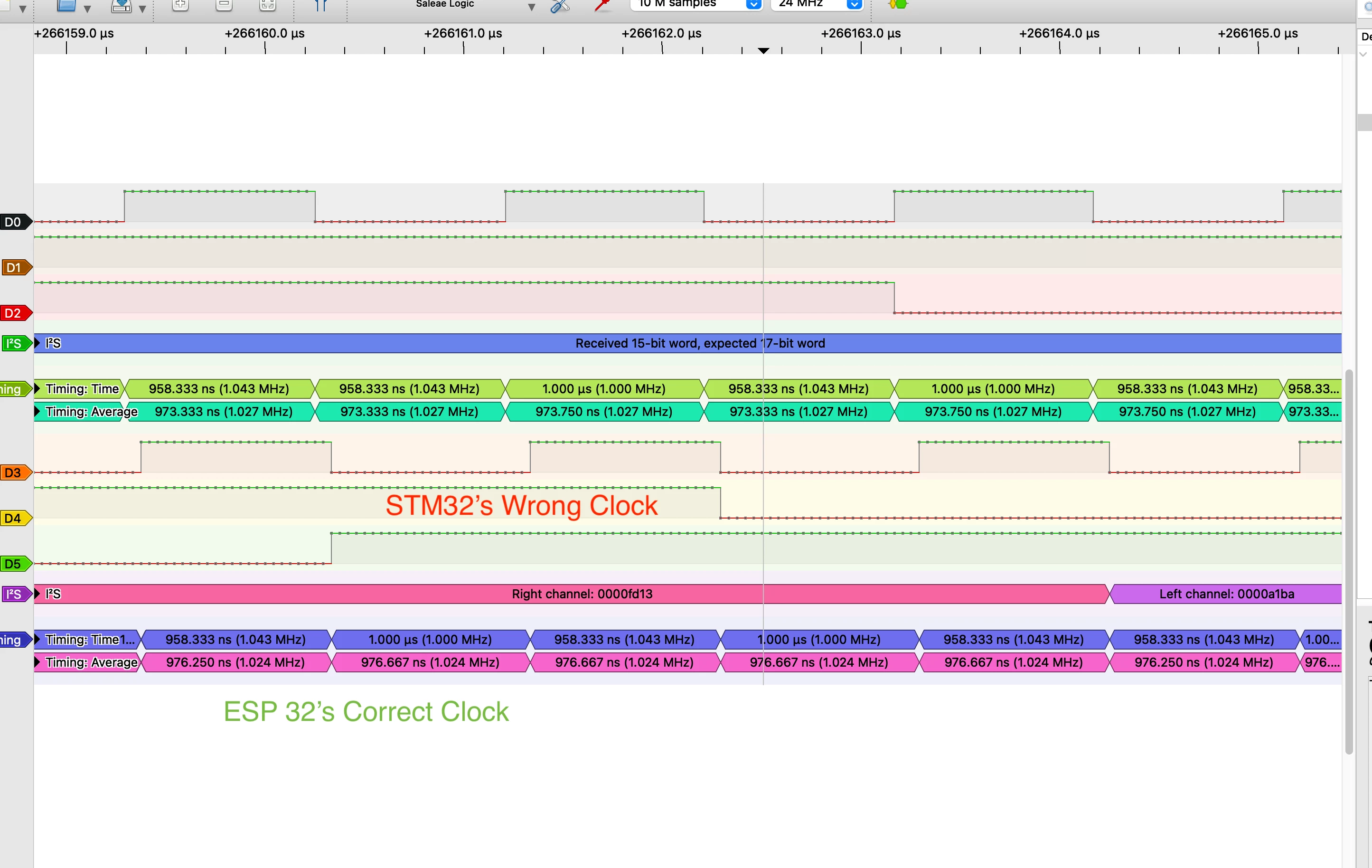
Much to my surprise, the STM32 is actually outputting 1.027 Mhz average clock pulses instead of the ESP32's 1.024 Mhz. 

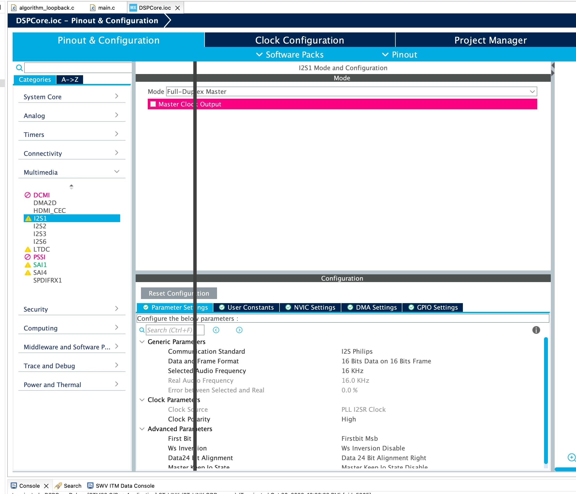
Checked the Clock in STM MX, shows 0% error and an input clock of 2.048 Mhz which is divisible. Tried also 20.48 Mhz with no change. There appears to be no divider settings. Any reason for this wrong output clock?
Screenshot 2023-10-30 at 12.29.16 PM.png


Screenshot 2023-10-30 at 12.29.37 PM.png


There are many "Expected 16 bit word, received 17 bit" etc, with varying bits because of the wrong clock. Expected is 16 bits.

 

Screenshot 2023-10-30 at 12.39.21 PM.png


This topic has been closed for replies.
Best answer by TDK

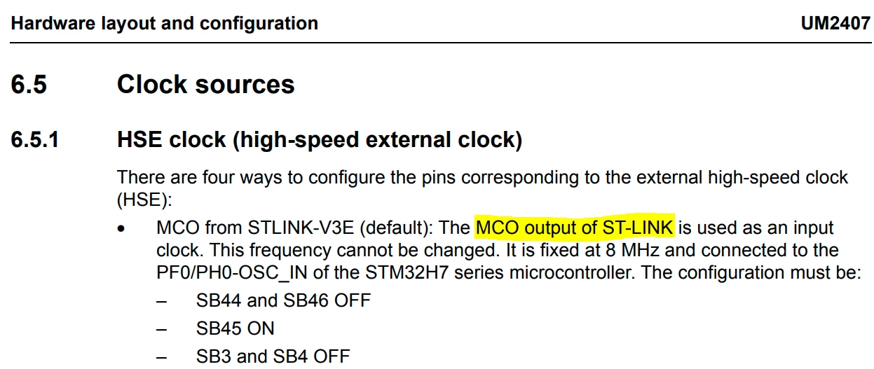
You're using the HSE bypass as clock, which is clocked from the HSI on the ST-Link chip. Yes, it's 8 MHz nominal, but not accurate to what a crystal would be. ±0.3% is well within the guaranteed accuracy range.

TDK_0-1698707228097.png

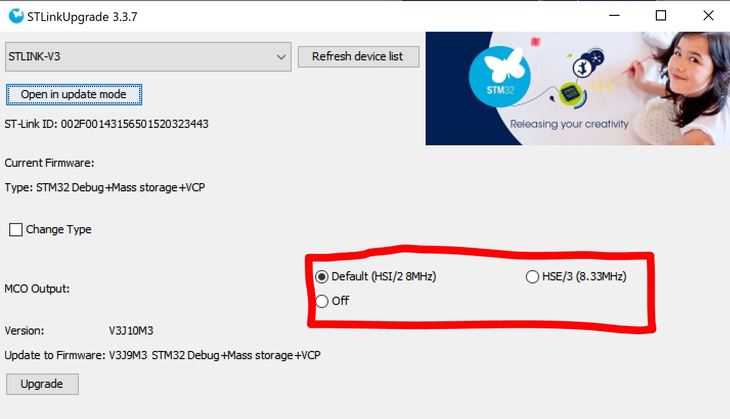
Despite what the user manual says, you can change this from the default HSI output to HSE output at 8.333MHz if you open the st-link in update mode and choose that option. You would then need to update your clock tree based on this new value.

TDK_1-1698707254389.png


10 replies

Tesla DeLorean
Guru
October 30, 2023

What board are you using?

Be aware that the ST-LINK/V3 doesn't output a pure 8 MHz normally, typically around 8.333 MHz based on it's 25 MHz clock, and DIV3 on the MCO pin feeding the target MCU

Tips, Buy me a coffee, or three.. PayPal Venmo (See Profile) Up vote any posts that you find helpful, it shows what's working..
Associate III
October 30, 2023

Hi @Tesla DeLorean,

Using the Nucleo H723ZG... According to the PDF I found here, the HSE looks to be 8Mhz. 

Here's the clock config with the HSI. It looks like its off even more now, at 1.029 Mhz pulses.

Screenshot 2023-10-30 at 3.48.45 PM.png

TDK
October 30, 2023

Also be aware that ±0.3% is well within the tolerance of the HSI. HSE will need to be used to be more accurate.

"If you feel a post has answered your question, please click ""Accept as Solution""."
TDK
TDKBest answer
October 30, 2023

You're using the HSE bypass as clock, which is clocked from the HSI on the ST-Link chip. Yes, it's 8 MHz nominal, but not accurate to what a crystal would be. ±0.3% is well within the guaranteed accuracy range.

TDK_0-1698707228097.png

Despite what the user manual says, you can change this from the default HSI output to HSE output at 8.333MHz if you open the st-link in update mode and choose that option. You would then need to update your clock tree based on this new value.

TDK_1-1698707254389.png


"If you feel a post has answered your question, please click ""Accept as Solution""."
Associate III
October 30, 2023

Okay, I'll try to change it to 8.33 the 8.33 option. Do you know the decimal places on this "8.33" or is it 8.33333333.

Edit: The only problem is there isn't a PLL combination I can come up with to output an accurate 2.048 signal now for the SAI bus (PDM mic) bus... 

TDK
October 30, 2023

It's 25/3 MHz.

"If you feel a post has answered your question, please click ""Accept as Solution""."
Piranha
Principal III
October 31, 2023

I2S, SPI and I2C have a clock signal, on which the data is sampled, and therefore those are synchronous interfaces. And for such interfaces a specific frequency doesn't matter. For I2S the SD is sampled on the rising SCK edge. That means the SD and WS must be changing at the falling SCK edge. In your second picture the ESP32 signal is correct, but for the STM32 signal either the SD or WS is changing on the rising SCK edge, which is wrong.


P.S. Full information about the STLINK-V3 provided MCO output:

https://community.st.com/t5/stm32-mcus-boards-and-hardware/how-to-change-the-stlink-v3e-mco-hse-frequency/td-p/218882

Associate III
October 31, 2023

Thanks everyone!

@TDK 

@Tesla DeLorean 

@Piranha 

Screenshot 2023-10-30 at 5.55.23 PM.png


Screenshot 2023-10-30 at 5.59.41 PM.png

LCE
Principal II
October 31, 2023

I don't like these 8.333 MHz... but these are much better than the HSI, which is unusable for audio >= 16 bit resolution.

BUT, there are the FRACN registers for each PLL for fine tuning, which get you close enough to the frequencies you need. (Even better, these can be modified on the fly.)

Anyway, I2S is not that complicated to set up, so for full control and to know what's going on, better use direct register settings.

Piranha
Principal III
November 1, 2023

The targeted 16 kHz sample rate in the screenshots points to this solution not requiring a Hi-Fi audio. Anyway I would avoid using PLL in fractional mode unless actually necessary. I the latest screenshots the author has already found the best rational fraction for PLL, which deviates from the ideal frequency by +11 ppm. Humans can detect a pitch variation of 0,3 % (3000 ppm) at best. And that is for a variation, not a constant offset! In other words - there is absolutely no point in using a fractional PLL mode and increasing the jitter unnecessarily.