


AE104
Associate III
March 17, 2023
Solved

SPI Signal Shape Issue

Hello,

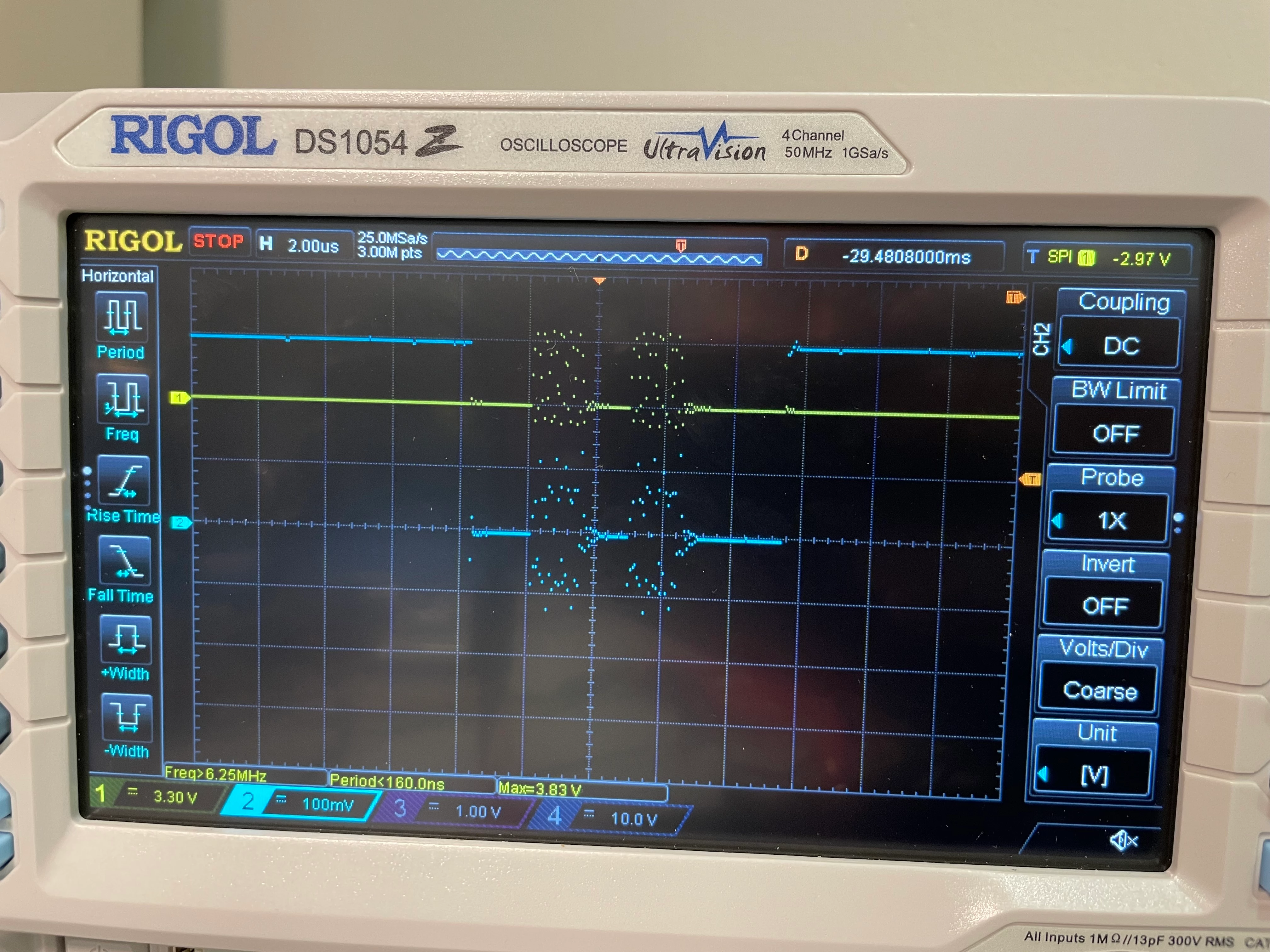
I am try to control an external DAC system with the SPI interface. The clock signal shape looks like the attached file. I didn't figure out the meaning of the signal. Yellow is the clock signal and the blue is CS signal.0693W00000aJE10QAG.jpg
This topic has been closed for replies.
AScha.3
AScha.3Best answer
Super User
March 17, 2023

yes. Need to change to something useful. set -> button Aquire-> mode:normal, mem-depth: auto , anti-alias:off ; + buton Display -> type: vector .

+

set your probe to x10 , an in dso probe menu also x10 setting.

(and it was NOT default setting ! )

if want some gaming: just try -- press button AUTO , with signal active; scope tries to set it then automatic good.

If you feel a post has answered your question, please click on " Best Answer ".

24 replies

Tesla DeLorean
Guru
March 17, 2023

Yes, looks awful, how is this wired up? Show a circuit diagram

Make sure the grounds are properly bonded across domains.

Tips, Buy me a coffee, or three.. PayPal Venmo (See Profile) Up vote any posts that you find helpful, it shows what's working..
AE104
AE104Author
Associate III
March 17, 2023

The reference manual of the chip is designed with the isolator, so I designed it based on that. Should I remove it? @Community member​ 

0693W00000aJE65QAG.png

Tesla DeLorean
Guru
March 17, 2023

And with the scope traces, which side are you probing here?

And which ground is the scope attached too?

Tips, Buy me a coffee, or three.. PayPal Venmo (See Profile) Up vote any posts that you find helpful, it shows what's working..
AE104
AE104Author
Associate III
March 17, 2023

I am probing the OUT side of the isolator. The yellow signal is the SCLK, and the blue is CS. The probing to the GND_ISO.

waclawek.jan
Super User
March 17, 2023

Why is scope set to 25MSa/s?

JW

AE104
AE104Author
Associate III
March 17, 2023

I assume it is default setting. Should I change it? If it is, how can I do that?

AScha.3
AScha.3Best answer
Super User
March 17, 2023

yes. Need to change to something useful. set -> button Aquire-> mode:normal, mem-depth: auto , anti-alias:off ; + buton Display -> type: vector .

+

set your probe to x10 , an in dso probe menu also x10 setting.

(and it was NOT default setting ! )

if want some gaming: just try -- press button AUTO , with signal active; scope tries to set it then automatic good.

If you feel a post has answered your question, please click on " Best Answer ".
AE104
AE104Author
Associate III
March 17, 2023

Now I just reflected your recommendations. These are the current signal shapes.

I will try to test without the isolator.

AScha.3
Super User
March 17, 2023

mmmm. something wrong - my sample rate is 500Ms at 2us/div.

(i have same DS1054 here, just 200MHz software in :) )

you have something totally wrong in settings - i cannot set so (useless) low rate , its greyed out.

did you try: AUTO button ? (or try: CLEAR , then AUTO , with active input signals)

here ...why dont use the dso print file ?? so:

0693W00000aJEOsQAO.png

If you feel a post has answered your question, please click on " Best Answer ".
AE104
AE104Author
Associate III
March 17, 2023

I pressed the CLEAR and AUTO, now the sampling rate is 250 MSa/s with 300k pts.

Tesla DeLorean
Guru
March 17, 2023

The bandwidth of the isolator is 25 Mbps

Is the signal on the STM32 side clean? Not ringing?

If the traces are short, ease back the slew-rate via SPEEDR settings.

What speed is your SPI clocking at?

Tips, Buy me a coffee, or three.. PayPal Venmo (See Profile) Up vote any posts that you find helpful, it shows what's working..
AE104
AE104Author
Associate III
March 17, 2023

Now the updated signals look like the attached figures (the isolator removed).

The SPI Baudrate 10.5 Mbits/s.0693W00000aJEfjQAG.jpg
