Tommino
Associate III
July 21, 2022
Solved

How to init SPI properly

Hi,

I am trying to init SPI1 (to just receive data qwith MISO) on nucleo G474RE without using HAL libraries.

Can you help me to assess why my code does not work ?

I can't see the clock eventhough SPI1 is enabled

_legacyfs_online_stmicro_images_0693W00000QLmdH.png
_legacyfs_online_stmicro_images_0693W00000QLmdR.png 

void SPI1_init(){
	RCC-> APB2ENR|=(1 AHB2ENR |= (1MODER &= ~(1 AFR[0] |= (1 AFR[0] |= (1 AFR[0] |= (1 CR1 |= (1 CR1 |= (1 CR1 |= (1 CR2 |=(1CR2 |= (1CR1|= (1CR1|= (1CR1&= ~(1

 

This topic has been closed for replies.
waclawek.jan
waclawek.janBest answer
Super User
July 22, 2022

> Again, I would suggest starting with HAL to see how that does it, then base your bare-metal on that ...

I would recommend completely forget about existence of Cube/HAL, first. Then read the fine manuals, thoroughly.

The Rx-only mode is being matter of grief, especially for those who click, as it requires to know what one is doing.

JW

20 replies

waclawek.jan
Super User
July 21, 2022

SPI1_SCK is PA5 and its MODER is set to 0b00 i.e. Input instead of 0b10 for AF.

Did not look further.

JW

Tommino
TomminoAuthor
Associate III
July 22, 2022

Hi @Community member​ 

thanks again.

I modified PA5 MODER to AF5 but there should be still something that blocks the SPI1..

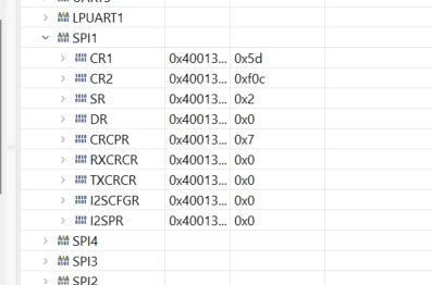
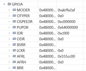
I doublechecked the GPIO and SPI clock, the GPIOsettings and SPI1 settings but I cannot find what is still wrong. Can you give a look to the registers again?

The code is just about enabling this SPI1 in order to see the SPI1 clock coming out from my NUCLEOG474RE

GPIOA has clock enalbled0693W00000QLrrsQAD.pngSPI1 clock enabled0693W00000QLrytQAD.pngPA4 PA5 and PA6 all alternate function AF50693W00000QLruIQAT.pngSPI registers

0693W00000QLrx7QAD.png

waclawek.jan
Super User
July 22, 2022

So you see still no clock on PA5 when you write into SPI1->DR, e.g. in debugger? How do the SPI registers change after that write?

I'm not sure what's the behaviour of the internal NSS node if you set SSOE as you've done. Try setting both SSM and SSI.

JW

Tommino
TomminoAuthor
Associate III
July 22, 2022

I found that the only way to see the SCK line activated is to write

while (1){

SPI1->DR= something;

}

if I write directly the registers while debugging the status register is affected (RXNE bit) but I cannot see the SCK outputs (in nucleo G474RE PA5 is connected to LED 2 so it is easy to see)

0693W00000QLsVJQA1.png 

Maybe this is the right behaviour of the SPI interface?

I thought that after enabling it I would have seen the SCK line activated even if I am not receving data

Andrew Neil
Super User
July 22, 2022

@Tommino​ "I thought that after enabling it I would have seen the SCK line activated even if I am not receving data"

No: the clock is generated by sending stuff out on MOSI - this is inherent to the way SPI works.

 EDIT:

Correction - See below: this chip has a special 'receive-only' mode

A complex system that works is invariably found to have evolved from a simple system that worked.A complex system designed from scratch never works and cannot be patched up to make it work.
Andrew Neil
Super User
July 22, 2022

@Tommino​ "without using HAL libraries"

I would suggest that you get it working with the HAL first - then you have a working example on which to base your bare-metal implementation.

A complex system that works is invariably found to have evolved from a simple system that worked.A complex system designed from scratch never works and cannot be patched up to make it work.
Tommino
TomminoAuthor
Associate III
July 22, 2022

First step with HAL done

Tommino
TomminoAuthor
Associate III
July 22, 2022

Hi @Andrew Neil​ 

But what if the uC needs only to receive data on MISO and also be the master of the communication? The uC shall generate the clock...

Andrew Neil
Super User
July 22, 2022

Ah, you're right - this one has a special 'receive-only' mode:

0693W00000QLsxmQAD.png 

Again, I would suggest starting with HAL to see how that does it, then base your bare-metal on that ...

A complex system that works is invariably found to have evolved from a simple system that worked.A complex system designed from scratch never works and cannot be patched up to make it work.
Andrew Neil
Super User
July 22, 2022

So have you set the RXONLY bit?

A complex system that works is invariably found to have evolved from a simple system that worked.A complex system designed from scratch never works and cannot be patched up to make it work.
Tommino
TomminoAuthor
Associate III
July 22, 2022

Thanks @Andrew Neil​ 

It was probably the RXONLY bit causing the issue. Now it is fine.

Andrew Neil
Super User
July 22, 2022

@Tommino​ "Now it is fine"

Good to hear - now please mark the solution:

0693W000008y9fZQAQ.png

A complex system that works is invariably found to have evolved from a simple system that worked.A complex system designed from scratch never works and cannot be patched up to make it work.
waclawek.jan
waclawek.janBest answer
Super User
July 22, 2022

> Again, I would suggest starting with HAL to see how that does it, then base your bare-metal on that ...

I would recommend completely forget about existence of Cube/HAL, first. Then read the fine manuals, thoroughly.

The Rx-only mode is being matter of grief, especially for those who click, as it requires to know what one is doing.

JW

Tommino
TomminoAuthor
Associate III
July 22, 2022

Hi @Community member​ ,

Thanks for your post in the blog.

What I understood is that you recommend to not connect the MOSI pin through AF if not needed. But then who controls when the clock is output on SCK? the SPI enable?

waclawek.jan
Super User
July 22, 2022

SCK does not depend on MOSI.

SPI in its most basic form are two shift registers - one for output one for input - and some control logic to generate clocks.

If SPI is set as master and enabled, and then you write to DR, the control logic generates 8 or 16 (or whatever you set) clocks on SPI, and using those clocks it shifts out data from output shift register to MOSI and shifts in data into input shift register from MISO.

If you don't assign any pin to MOSI in GPIO, well simply the internal MOSI output from SPI module is connected nowhere and the shifted out data are lost. If you don't assign any pin to MISO in GPIO, the internal MISO input to SPI module is set to 0, so you will simply receive all zeros.

The mode which is set by RXONLY bit is already an extension to this basic model - if you set that bit, as soon as SPI is enabled, the control logic starts to generate clocks and it won't stop until SPI is disabled.