Associate II
May 10, 2025
Solved

FDCAN FIFO full

  • May 10, 2025
  • 10 replies
  • 2431 views

I am using a custom PCB with stm32g474 and I am trying to get the CAN peripheral working. I believe I have everything set up correctly (bit rate, RAM etc) but when I call HAL_FDCAN_AddMessageToTxFifoQ(), FIFO is full error is raised after 3 iterations.

Any help is appreciated.

This topic has been closed for replies.
Best answer by mƎALLEm

OK now the picture is clear. I don't see an issue in your CAN configuration.

Meanwhile:

1- It's recommended to use HSE with an external crystal instead of using HSI. But in your project you are selectiong HSI as clock source for PLL for both projects:
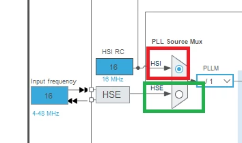
 

mALLEm_1-1747054446755.png

2- From your schematics you still using a 10K resistor in series with the crystal while I said in your previous post here this is a big value for a series resistor. You need to calculate it or simply shunt it.

So please use the external resistor with a very low resistor value.

3- I also recommend to check the CAN_H and CAN_L connections. Connect the cable between the boards and use a continuity tester and check the connection of CAN_H/CAN_L on the transceivers' pins. Not on the cable or the connector but on the transceivers' pins.


 

10 replies

MHoll.2
Senior III
May 11, 2025

Can You confirm that You have a working CAN-bus (2x120R Termination, and at least 1 other node that is working, for example a CANBus dongle)?

Why do You use a isolated CANBus driver when You use the same ground (and 5V) on both side of the isolation?

Associate II
May 12, 2025

I will conform the working CAN-bus.

Can you please give the correct circuit for ADM3050EBRIZ transceiver. Or any other IC I can use instead.  

mƎALLEm
ST Technical Moderator
May 12, 2025

ADM3050EBRIZ looks good even excellent as it has the isolation capability between both sides digital and the bus.

So question still: what did you connect to the CAN bus apart that node (STM32G474+ADM3050)? and why is there a 1.5k ohm connected on the CAN_H and CAN_L on the tranceiver pins? it should be 120 ohm. 

Also only two 120ohm are termination the bus.

Refer to this article: STM32 FDCAN running at 8 Mb/s on NUCLEO boards


To give better visibility on the answered topics, please click "Best answer" on the reply which solved your issue or answered your question.
ST Technical Moderator
May 12, 2025

Hello @ChaitanyaParate 

Could you describe your setup with more details please, your FDCAN peripheral is communicating with which device? 

Did you check to compare your configuration and setup with the example below: 

STM32CubeG4/Projects/STM32G474E-EVAL/Examples/FDCAN/FDCAN_Com_polling at master · STMicroelectronics/STM32CubeG4 · GitHub

In order to give better visibility on the answered topics, please click on 'Best answer' on the reply which solved your issue or answered your question. Saket_Om
mƎALLEm
ST Technical Moderator
May 12, 2025

Hello,

Same question as @MHoll.2 

+ Could you please explain this hardware?:

mALLEm_0-1747038901038.png

Why are you using a 1.5k on CAN_H and CAN_L lines? and how are you connecting these two lines externally?

Also explain the diference between the two attached software: FDCAN_receive.zip and FDCAN_F.zip.

 
To give better visibility on the answered topics, please click "Best answer" on the reply which solved your issue or answered your question.