Solved
STM32H750 ADC calibration routine fails
Not using calibration rotines
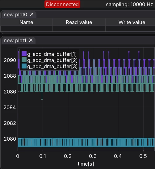
VS using them:
MX_GPIO_Init();

MX_DMA_Init();

MX_ADC1_Init();

MX_ADC2_Init();

MX_TIM15_Init();

MX_TIM6_Init();

/* USER CODE BEGIN 2 */

// 1. Initialize Profiler hardware

profiler_init();

profiler_reset(&g_isr_profiler);

setupRecorder();


// HAL_ADCEx_LinearCalibration_FactorLoad(&hadc1);

// HAL_ADCEx_LinearCalibration_FactorLoad(&hadc2);

if (HAL_ADCEx_Calibration_Start(&hadc1, ADC_CALIB_OFFSET_LINEARITY, ADC_DIFFERENTIAL_ENDED) != HAL_OK)

Error_Handler();

if (HAL_ADCEx_Calibration_Start(&hadc2, ADC_CALIB_OFFSET_LINEARITY, ADC_DIFFERENTIAL_ENDED) != HAL_OK)

Error_Handler();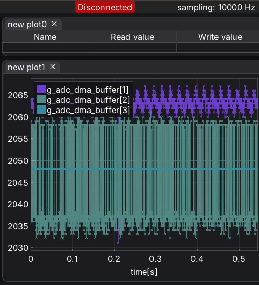
As you can see the HAL library calibration made it worth instead of healing it.
Then what is the right solution to calibrate? What is the problem here? I’ve used linear and offset only both introduced jumping on the short circuited signal.
I wanted to ask ST please be responsible for this artifact, andit to your errata sheet if required, please.
Main file:
/* USER CODE BEGIN Header */
	/**
	  ******************************************************************************
	  * @file           : main.c
	  * @brief          : Main program body
	  ******************************************************************************
	  * @attention
	  *
	  * Copyright (c) 2026 STMicroelectronics.
	  * All rights reserved.
	  *
	  * This software is licensed under terms that can be found in the LICENSE file
	  * in the root directory of this software component.
	  * If no LICENSE file comes with this software, it is provided AS-IS.
	  *
	  ******************************************************************************
	  */
/* USER CODE END Header */
/* Includes ------------------------------------------------------------------*/
#include "main.h"

/* Private includes ----------------------------------------------------------*/
/* USER CODE BEGIN Includes */
#include "dwt_profiler.h"
#include "inc_encoder_processor.h"
#include "recorder.h"
#include "sincos_system.h"
#include "flash_manager.h"
/* USER CODE END Includes */

/* Private typedef -----------------------------------------------------------*/
/* USER CODE BEGIN PTD */

/* USER CODE END PTD */

/* Private define ------------------------------------------------------------*/
/* USER CODE BEGIN PD */
	#define BLOCK_SIZE 1
	#define BUFFER_SIZE (BLOCK_SIZE * 2)
/* USER CODE END PD */

/* Private macro -------------------------------------------------------------*/
/* USER CODE BEGIN PM */

/* USER CODE END PM */

/* Private variables ---------------------------------------------------------*/
ADC_HandleTypeDef hadc1;
ADC_HandleTypeDef hadc2;
DMA_HandleTypeDef hdma_adc1;

TIM_HandleTypeDef htim6;
TIM_HandleTypeDef htim15;

/* USER CODE BEGIN PV */
__attribute__((aligned(4))) volatile uint16_t g_adc_dma_buffer[4] = {0};
static profiler_stat_t g_isr_profiler;
static sincos_system_t g_sys;
// Instantiate the top-level aggregator and the profiler handle

static float adc_signed_sin_normalized __attribute__((used));
static float adc_signed_cos_normalized __attribute__((used));
static float adc_signed_sin_normalized_abs __attribute__((used));
static float adc_signed_cos_normalized_abs __attribute__((used));
static uint16_t adc_signed_sin_buff_abs __attribute__((used));
static uint16_t adc_signed_cos_buff_abs __attribute__((used));
static float residual_error __attribute__((used));

/* USER CODE END PV */

/* Private function prototypes -----------------------------------------------*/
void SystemClock_Config(void);
void PeriphCommonClock_Config(void);
static void MPU_Config(void);
static void MX_GPIO_Init(void);
static void MX_DMA_Init(void);
static void MX_ADC1_Init(void);
static void MX_ADC2_Init(void);
static void MX_TIM15_Init(void);
static void MX_TIM6_Init(void);
/* USER CODE BEGIN PFP */

/* USER CODE END PFP */

/* Private user code ---------------------------------------------------------*/
/* USER CODE BEGIN 0 */
	extern ____Recorder ____recorder;
	void setupRecorder(void)
	{
		// 1. Set the recorder state to RUNNING
		____recorder.state = ____STATE_RUNNING;

		// 2. Define which variables to record
		//    The 'size' is the size of the variable in BYTES.
	//    ____recorder.variableCount = 1;

	//    ____recorder.sampleList[0].address = (uint32_t)&g_encoder_engine.ekf_speed_rpm;
	//    ____recorder.sampleList[0].size    = sizeof(g_encoder_engine.ekf_speed_rpm); // 4 bytes

	//    ____recorder.sampleList[1].address = (uint32_t)&myAdcValue;
	//    ____recorder.sampleList[1].size    = sizeof(myAdcValue); // 4 bytes

	//    ____recorder.sampleList[2].address = (uint32_t)&myTemperature;
	//    ____recorder.sampleList[2].size    = sizeof(myTemperature); // 4 bytes

		// 3. (Optional) Calculate the total size of one sample pack
		//    This is useful for buffer management but not strictly required.
		____recorder.samplesPackSize = 4 + 4 + 4; // 10 bytes per sample

		// 4. Set the maximum buffer size (usually matches ____RECORDER_BUFFERSIZE)
		____recorder.maxActualBufferSize = ____RECORDER_BUFFERSIZE;

		// 5. (Optional) Configure a trigger
		//    Example: Trigger on rising edge of myCounter when it exceeds 1000
		// ____recorder.trigger.state = ____STATE_READY;
		// ____recorder.trigger.type = ____U32;
		// ____recorder.trigger.edge = ____EDGE_RISING;
		// ____recorder.trigger.sourceAddress = (uint32_t)&myCounter;
		// ____recorder.trigger.triggerValueU32 = 1000;
		// ____recorder.trigger.preTriggerSamples = 50; // Capture 50 samples before trigger
	}
/* USER CODE END 0 */

/**
  * @brief  The application entry point.
  * @retval int
  */
int main(void)
{

  /* USER CODE BEGIN 1 */


  /* USER CODE END 1 */

  /* MPU Configuration--------------------------------------------------------*/
  MPU_Config();

  /* MCU Configuration--------------------------------------------------------*/

  /* Reset of all peripherals, Initializes the Flash interface and the Systick. */
  HAL_Init();

  /* USER CODE BEGIN Init */

  /* USER CODE END Init */

  /* Configure the system clock */
  SystemClock_Config();

  /* Configure the peripherals common clocks */
  PeriphCommonClock_Config();

  /* USER CODE BEGIN SysInit */

  /* USER CODE END SysInit */

  /* Initialize all configured peripherals */
  MX_GPIO_Init();
  MX_DMA_Init();
  MX_ADC1_Init();
  MX_ADC2_Init();
  MX_TIM15_Init();
  MX_TIM6_Init();
  /* USER CODE BEGIN 2 */
  // 1. Initialize Profiler hardware
  profiler_init();
  profiler_reset(&g_isr_profiler);
  setupRecorder();

//  HAL_ADCEx_LinearCalibration_FactorLoad(&hadc1);
//  HAL_ADCEx_LinearCalibration_FactorLoad(&hadc2);
  if (HAL_ADCEx_Calibration_Start(&hadc1, ADC_CALIB_OFFSET_LINEARITY, ADC_DIFFERENTIAL_ENDED) != HAL_OK)
      Error_Handler();
  if (HAL_ADCEx_Calibration_Start(&hadc2, ADC_CALIB_OFFSET_LINEARITY, ADC_DIFFERENTIAL_ENDED) != HAL_OK)
      Error_Handler();
//  if (HAL_ADCEx_Calibration_Start(&hadc1, ADC_CALIB_OFFSET, ADC_DIFFERENTIAL_ENDED) != HAL_OK)
//	  Error_Handler();
//  if (HAL_ADCEx_Calibration_Start(&hadc2, ADC_CALIB_OFFSET, ADC_DIFFERENTIAL_ENDED) != HAL_OK)
//	  Error_Handler();

  /* Flash manager first — sincos_system_load_from_flash needs it */
  (void)flash_manager_init();
  float adc_norm;
  			const float FULL_SCALE_16B = 5000.0f;   /* your reference divisor for 16-bit */
  			switch (hadc1.Init.Resolution)
  			{
  				case ADC_RESOLUTION_16B:

  					adc_norm = FULL_SCALE_16B;                          /* >> 0 */
  					break;

  				case ADC_RESOLUTION_14B:

  					adc_norm = (FULL_SCALE_16B / 4.0f);                 /* >> 2 */
  					break;

  				case ADC_RESOLUTION_12B:

  					adc_norm = (FULL_SCALE_16B / 16.0f);                /* >> 4 */
  					break;

  				case ADC_RESOLUTION_10B:

  					adc_norm = (FULL_SCALE_16B / 64.0f);                /* >> 6 */
  					break;

  				case ADC_RESOLUTION_8B:

  					adc_norm = (FULL_SCALE_16B / 256.0f);               /* >> 8 */
  					break;

  				default:

  					adc_norm = 0.0f;
  					break;
  			}
  			uint32_t adc_mid=0;
  			switch (hadc1.Init.Resolution)
  			{
  			case ADC_RESOLUTION_16B:
  				adc_mid=32768;/* 2^15 */
  				break;

  			case ADC_RESOLUTION_14B:
  				adc_mid=8192; /* 2^13 */
  				break;

  			case ADC_RESOLUTION_12B:
  				adc_mid=2048; /* 2^11 */
  				break;

  			case ADC_RESOLUTION_10B:
  				adc_mid=512; /* 2^9 */
  				break;

  			case ADC_RESOLUTION_8B:
  				adc_mid=128;  /* 2^7 */
  				break;

  			default:
  				adc_mid = 0;
  				break;
  			}
  /* Sincos system — must init before TIM15 IC interrupts are enabled */
  sincos_system_config_t sys_cfg = {
      .ts                        = 1.0f / 10000.0f,
      .lines_per_rev             = 2048u,
      .expected_phase_at_R       = 0.0f,
      .offset_init               = 0.0f,
      .r_edge_timer              = &htim15,
      .ppa_cfg                   = NULL,

      /* A/B: 12-bit, midpoint 2048, full scale 5000 → scale = 1 / (5000/16) = 16/5000 */
      .inc_raw_to_unit_scale     = 1 / adc_norm,
      .inc_raw_midpoint          = adc_mid,

      /* C/D: same resolution, midpoint 2048 */
      .abs_raw_to_unit_scale     = 1 / adc_norm,
      .abs_raw_midpoint          = adc_mid,

      .abs_sample_period         = 100u,
      .continue_on_abs_fault     = true,
      .continue_on_turn_overflow = true,

	  /* ---- LMS calibration FSM thresholds ---------------------------
	   *
	   * Every one of the four fields below is **required** for the FSM
	   * to behave as documented in `sincos_system.h`. Designated-
	   * initializer semantics leave unset fields at 0, which for these
	   * values means:
	   *
	   *   lms_save_threshold  = 0  → nothing ever counts as "converged"
	   *   lms_drift_threshold = 0  → every nonzero residual fires DRIFTED
	   *   lms_conv_samples    = 0  → the very first low-residual sample
	   *                              fires CALIBRATED → immediate save
	   *   lms_min_rpm         = 0  → the A/B motion gate is always shut
	   *                              (and with the `lms_adapt_gate` fix
	   *                              in inc_encoder_processor.c, it is
	   *                              correctly shut — but that means the
	   *                              A/B LMS never adapts, so it can
	   *                              never converge either).
	   *
	   * The values below are the production tuning: a ~3x hysteresis
	   * band, a convergence window long enough to reject transient
	   * lucky points, a motion floor that forces the shaft to actually
	   * rotate, and a 10 s timeout for the health flag.
	   * -------------------------------------------------------------- */


      .lms_save_threshold        = 0.05f,

	  .lms_drift_threshold       = 0.15f,
	  .lms_conv_samples          = 2000u,
	  .lms_min_rpm               = 6.0f,

	  /* ---- Convergence timeout (SINCOS_FAULT_LMS_CONV_TIMEOUT) ------
	   *
	   * 100 000 ticks = 10 s at the 10 kHz ADC rate. Long enough that a
	   * normal cold start (converges in well under 1 s of motion) never
	   * trips it. Short enough that a stuck LMS — wrong tuning, a
	   * disconnected channel, or a shaft that never spins — surfaces
	   * while the operator is still looking at the machine.
	   *
	   * Pass 0 to disable the feature. See sincos_system.h.
	   * -------------------------------------------------------------- */
	  .lms_conv_timeout_samples  = 100000u,
  };

  sincos_system_init(&g_sys, &sys_cfg);
//  sincos_system_load_defaults(&g_sys);
  sincos_system_load_from_flash(&g_sys);

  /* Start the timer that will trigger the ADC */
  /* Now safe to enable interrupts */
  if (HAL_TIM_Base_Start(&htim15) != HAL_OK)
      Error_Handler();

  HAL_TIM_IC_Start_IT(&htim15, TIM_CHANNEL_1);
  HAL_TIM_IC_Start_IT(&htim15, TIM_CHANNEL_2);

  if (HAL_ADCEx_MultiModeStart_DMA(&hadc1, (uint32_t*)g_adc_dma_buffer, 2) != HAL_OK)
      Error_Handler();


  /* USER CODE END 2 */

  /* Infinite loop */
  /* USER CODE BEGIN WHILE */
	  while (1)
	  {
    /* USER CODE END WHILE */

    /* USER CODE BEGIN 3 */

	  }
  /* USER CODE END 3 */
}

/**
  * @brief System Clock Configuration
  * @retval None
  */
void SystemClock_Config(void)
{
  RCC_OscInitTypeDef RCC_OscInitStruct = {0};
  RCC_ClkInitTypeDef RCC_ClkInitStruct = {0};

  /** Supply configuration update enable
  */
  HAL_PWREx_ConfigSupply(PWR_LDO_SUPPLY);

  /** Configure the main internal regulator output voltage
  */
  __HAL_PWR_VOLTAGESCALING_CONFIG(PWR_REGULATOR_VOLTAGE_SCALE3);

  while(!__HAL_PWR_GET_FLAG(PWR_FLAG_VOSRDY)) {}

  /** Initializes the RCC Oscillators according to the specified parameters
  * in the RCC_OscInitTypeDef structure.
  */
  RCC_OscInitStruct.OscillatorType = RCC_OSCILLATORTYPE_HSE;
  RCC_OscInitStruct.HSEState = RCC_HSE_ON;
  RCC_OscInitStruct.PLL.PLLState = RCC_PLL_ON;
  RCC_OscInitStruct.PLL.PLLSource = RCC_PLLSOURCE_HSE;
  RCC_OscInitStruct.PLL.PLLM = 5;
  RCC_OscInitStruct.PLL.PLLN = 40;
  RCC_OscInitStruct.PLL.PLLP = 2;
  RCC_OscInitStruct.PLL.PLLQ = 2;
  RCC_OscInitStruct.PLL.PLLR = 2;
  RCC_OscInitStruct.PLL.PLLRGE = RCC_PLL1VCIRANGE_2;
  RCC_OscInitStruct.PLL.PLLVCOSEL = RCC_PLL1VCOWIDE;
  RCC_OscInitStruct.PLL.PLLFRACN = 0;
  if (HAL_RCC_OscConfig(&RCC_OscInitStruct) != HAL_OK)
  {
    Error_Handler();
  }

  /** Initializes the CPU, AHB and APB buses clocks
  */
  RCC_ClkInitStruct.ClockType = RCC_CLOCKTYPE_HCLK|RCC_CLOCKTYPE_SYSCLK
                              |RCC_CLOCKTYPE_PCLK1|RCC_CLOCKTYPE_PCLK2
                              |RCC_CLOCKTYPE_D3PCLK1|RCC_CLOCKTYPE_D1PCLK1;
  RCC_ClkInitStruct.SYSCLKSource = RCC_SYSCLKSOURCE_PLLCLK;
  RCC_ClkInitStruct.SYSCLKDivider = RCC_SYSCLK_DIV1;
  RCC_ClkInitStruct.AHBCLKDivider = RCC_HCLK_DIV1;
  RCC_ClkInitStruct.APB3CLKDivider = RCC_APB3_DIV1;
  RCC_ClkInitStruct.APB1CLKDivider = RCC_APB1_DIV1;
  RCC_ClkInitStruct.APB2CLKDivider = RCC_APB2_DIV1;
  RCC_ClkInitStruct.APB4CLKDivider = RCC_APB4_DIV1;

  if (HAL_RCC_ClockConfig(&RCC_ClkInitStruct, FLASH_LATENCY_2) != HAL_OK)
  {
    Error_Handler();
  }
}

/**
  * @brief Peripherals Common Clock Configuration
  * @retval None
  */
void PeriphCommonClock_Config(void)
{
  RCC_PeriphCLKInitTypeDef PeriphClkInitStruct = {0};

  /** Initializes the peripherals clock
  */
  PeriphClkInitStruct.PeriphClockSelection = RCC_PERIPHCLK_ADC;
  PeriphClkInitStruct.PLL2.PLL2M = 5;
  PeriphClkInitStruct.PLL2.PLL2N = 32;
  PeriphClkInitStruct.PLL2.PLL2P = 2;
  PeriphClkInitStruct.PLL2.PLL2Q = 2;
  PeriphClkInitStruct.PLL2.PLL2R = 2;
  PeriphClkInitStruct.PLL2.PLL2RGE = RCC_PLL2VCIRANGE_2;
  PeriphClkInitStruct.PLL2.PLL2VCOSEL = RCC_PLL2VCOMEDIUM;
  PeriphClkInitStruct.PLL2.PLL2FRACN = 0;
  PeriphClkInitStruct.AdcClockSelection = RCC_ADCCLKSOURCE_PLL2;
  if (HAL_RCCEx_PeriphCLKConfig(&PeriphClkInitStruct) != HAL_OK)
  {
    Error_Handler();
  }
}

/**
  * @brief ADC1 Initialization Function
  * @param None
  * @retval None
  */
static void MX_ADC1_Init(void)
{

  /* USER CODE BEGIN ADC1_Init 0 */

  /* USER CODE END ADC1_Init 0 */

  ADC_MultiModeTypeDef multimode = {0};
  ADC_ChannelConfTypeDef sConfig = {0};

  /* USER CODE BEGIN ADC1_Init 1 */

  /* USER CODE END ADC1_Init 1 */

  /** Common config
  */
  hadc1.Instance = ADC1;
  hadc1.Init.ClockPrescaler = ADC_CLOCK_ASYNC_DIV2;
  hadc1.Init.Resolution = ADC_RESOLUTION_12B;
  hadc1.Init.ScanConvMode = ADC_SCAN_ENABLE;
  hadc1.Init.EOCSelection = ADC_EOC_SEQ_CONV;
  hadc1.Init.LowPowerAutoWait = DISABLE;
  hadc1.Init.ContinuousConvMode = DISABLE;
  hadc1.Init.NbrOfConversion = 2;
  hadc1.Init.DiscontinuousConvMode = DISABLE;
  hadc1.Init.ExternalTrigConv = ADC_EXTERNALTRIG_T15_TRGO;
  hadc1.Init.ExternalTrigConvEdge = ADC_EXTERNALTRIGCONVEDGE_RISING;
  hadc1.Init.ConversionDataManagement = ADC_CONVERSIONDATA_DMA_CIRCULAR;
  hadc1.Init.Overrun = ADC_OVR_DATA_OVERWRITTEN;
  hadc1.Init.LeftBitShift = ADC_LEFTBITSHIFT_NONE;
  hadc1.Init.OversamplingMode = DISABLE;
  hadc1.Init.Oversampling.Ratio = 1;
  if (HAL_ADC_Init(&hadc1) != HAL_OK)
  {
    Error_Handler();
  }

  /** Configure the ADC multi-mode
  */
  multimode.Mode = ADC_DUALMODE_REGSIMULT;
  multimode.DualModeData = ADC_DUALMODEDATAFORMAT_32_10_BITS;
  multimode.TwoSamplingDelay = ADC_TWOSAMPLINGDELAY_1CYCLE;
  if (HAL_ADCEx_MultiModeConfigChannel(&hadc1, &multimode) != HAL_OK)
  {
    Error_Handler();
  }

  /** Configure Regular Channel
  */
  sConfig.Channel = ADC_CHANNEL_3;
  sConfig.Rank = ADC_REGULAR_RANK_1;
  sConfig.SamplingTime = ADC_SAMPLETIME_64CYCLES_5;
  sConfig.SingleDiff = ADC_DIFFERENTIAL_ENDED;
  sConfig.OffsetNumber = ADC_OFFSET_NONE;
  sConfig.Offset = 0;
  sConfig.OffsetSignedSaturation = DISABLE;
  if (HAL_ADC_ConfigChannel(&hadc1, &sConfig) != HAL_OK)
  {
    Error_Handler();
  }

  /** Configure Regular Channel
  */
  sConfig.Channel = ADC_CHANNEL_5;
  sConfig.Rank = ADC_REGULAR_RANK_2;
  sConfig.SamplingTime = ADC_SAMPLETIME_32CYCLES_5;
  if (HAL_ADC_ConfigChannel(&hadc1, &sConfig) != HAL_OK)
  {
    Error_Handler();
  }
  /* USER CODE BEGIN ADC1_Init 2 */

  /* USER CODE END ADC1_Init 2 */

}

/**
  * @brief ADC2 Initialization Function
  * @param None
  * @retval None
  */
static void MX_ADC2_Init(void)
{

  /* USER CODE BEGIN ADC2_Init 0 */

  /* USER CODE END ADC2_Init 0 */

  ADC_ChannelConfTypeDef sConfig = {0};

  /* USER CODE BEGIN ADC2_Init 1 */

  /* USER CODE END ADC2_Init 1 */

  /** Common config
  */
  hadc2.Instance = ADC2;
  hadc2.Init.ClockPrescaler = ADC_CLOCK_ASYNC_DIV2;
  hadc2.Init.Resolution = ADC_RESOLUTION_12B;
  hadc2.Init.ScanConvMode = ADC_SCAN_ENABLE;
  hadc2.Init.EOCSelection = ADC_EOC_SEQ_CONV;
  hadc2.Init.LowPowerAutoWait = DISABLE;
  hadc2.Init.ContinuousConvMode = DISABLE;
  hadc2.Init.NbrOfConversion = 2;
  hadc2.Init.DiscontinuousConvMode = DISABLE;
  hadc2.Init.ConversionDataManagement = ADC_CONVERSIONDATA_DR;
  hadc2.Init.Overrun = ADC_OVR_DATA_OVERWRITTEN;
  hadc2.Init.LeftBitShift = ADC_LEFTBITSHIFT_NONE;
  hadc2.Init.OversamplingMode = DISABLE;
  hadc2.Init.Oversampling.Ratio = 1;
  if (HAL_ADC_Init(&hadc2) != HAL_OK)
  {
    Error_Handler();
  }

  /** Configure Regular Channel
  */
  sConfig.Channel = ADC_CHANNEL_4;
  sConfig.Rank = ADC_REGULAR_RANK_1;
  sConfig.SamplingTime = ADC_SAMPLETIME_64CYCLES_5;
  sConfig.SingleDiff = ADC_DIFFERENTIAL_ENDED;
  sConfig.OffsetNumber = ADC_OFFSET_NONE;
  sConfig.Offset = 25;
  if (HAL_ADC_ConfigChannel(&hadc2, &sConfig) != HAL_OK)
  {
    Error_Handler();
  }

  /** Configure Regular Channel
  */
  sConfig.Channel = ADC_CHANNEL_10;
  sConfig.Rank = ADC_REGULAR_RANK_2;
  sConfig.SamplingTime = ADC_SAMPLETIME_32CYCLES_5;
  sConfig.Offset = 0;
  if (HAL_ADC_ConfigChannel(&hadc2, &sConfig) != HAL_OK)
  {
    Error_Handler();
  }
  /* USER CODE BEGIN ADC2_Init 2 */

  /* USER CODE END ADC2_Init 2 */

}

/**
  * @brief TIM6 Initialization Function
  * @param None
  * @retval None
  */
static void MX_TIM6_Init(void)
{

  /* USER CODE BEGIN TIM6_Init 0 */

  /* USER CODE END TIM6_Init 0 */

  TIM_MasterConfigTypeDef sMasterConfig = {0};

  /* USER CODE BEGIN TIM6_Init 1 */

  /* USER CODE END TIM6_Init 1 */
  htim6.Instance = TIM6;
  htim6.Init.Prescaler = 10;
  htim6.Init.CounterMode = TIM_COUNTERMODE_UP;
  htim6.Init.Period = 9999;
  htim6.Init.AutoReloadPreload = TIM_AUTORELOAD_PRELOAD_DISABLE;
  if (HAL_TIM_Base_Init(&htim6) != HAL_OK)
  {
    Error_Handler();
  }
  sMasterConfig.MasterOutputTrigger = TIM_TRGO_UPDATE;
  sMasterConfig.MasterSlaveMode = TIM_MASTERSLAVEMODE_DISABLE;
  if (HAL_TIMEx_MasterConfigSynchronization(&htim6, &sMasterConfig) != HAL_OK)
  {
    Error_Handler();
  }
  /* USER CODE BEGIN TIM6_Init 2 */

  /* USER CODE END TIM6_Init 2 */

}

/**
  * @brief TIM15 Initialization Function
  * @param None
  * @retval None
  */
static void MX_TIM15_Init(void)
{

  /* USER CODE BEGIN TIM15_Init 0 */

  /* USER CODE END TIM15_Init 0 */

  TIM_MasterConfigTypeDef sMasterConfig = {0};
  TIM_IC_InitTypeDef sConfigIC = {0};

  /* USER CODE BEGIN TIM15_Init 1 */

  /* USER CODE END TIM15_Init 1 */
  htim15.Instance = TIM15;
  htim15.Init.Prescaler = 0;
  htim15.Init.CounterMode = TIM_COUNTERMODE_UP;
  htim15.Init.Period = 9999;
  htim15.Init.ClockDivision = TIM_CLOCKDIVISION_DIV1;
  htim15.Init.RepetitionCounter = 0;
  htim15.Init.AutoReloadPreload = TIM_AUTORELOAD_PRELOAD_DISABLE;
  if (HAL_TIM_IC_Init(&htim15) != HAL_OK)
  {
    Error_Handler();
  }
  sMasterConfig.MasterOutputTrigger = TIM_TRGO_UPDATE;
  sMasterConfig.MasterSlaveMode = TIM_MASTERSLAVEMODE_DISABLE;
  if (HAL_TIMEx_MasterConfigSynchronization(&htim15, &sMasterConfig) != HAL_OK)
  {
    Error_Handler();
  }
  sConfigIC.ICPolarity = TIM_INPUTCHANNELPOLARITY_RISING;
  sConfigIC.ICSelection = TIM_ICSELECTION_DIRECTTI;
  sConfigIC.ICPrescaler = TIM_ICPSC_DIV1;
  sConfigIC.ICFilter = 0;
  if (HAL_TIM_IC_ConfigChannel(&htim15, &sConfigIC, TIM_CHANNEL_1) != HAL_OK)
  {
    Error_Handler();
  }
  sConfigIC.ICPolarity = TIM_INPUTCHANNELPOLARITY_FALLING;
  sConfigIC.ICSelection = TIM_ICSELECTION_INDIRECTTI;
  if (HAL_TIM_IC_ConfigChannel(&htim15, &sConfigIC, TIM_CHANNEL_2) != HAL_OK)
  {
    Error_Handler();
  }
  /* USER CODE BEGIN TIM15_Init 2 */

  /* USER CODE END TIM15_Init 2 */

}

/**
  * Enable DMA controller clock
  */
static void MX_DMA_Init(void)
{

  /* DMA controller clock enable */
  __HAL_RCC_DMA1_CLK_ENABLE();

  /* DMA interrupt init */
  /* DMA1_Stream0_IRQn interrupt configuration */
  HAL_NVIC_SetPriority(DMA1_Stream0_IRQn, 0, 0);
  HAL_NVIC_EnableIRQ(DMA1_Stream0_IRQn);

}

/**
  * @brief GPIO Initialization Function
  * @param None
  * @retval None
  */
static void MX_GPIO_Init(void)
{
  GPIO_InitTypeDef GPIO_InitStruct = {0};
  /* USER CODE BEGIN MX_GPIO_Init_1 */

  /* USER CODE END MX_GPIO_Init_1 */

  /* GPIO Ports Clock Enable */
  __HAL_RCC_GPIOE_CLK_ENABLE();
  __HAL_RCC_GPIOH_CLK_ENABLE();
  __HAL_RCC_GPIOC_CLK_ENABLE();
  __HAL_RCC_GPIOA_CLK_ENABLE();
  __HAL_RCC_GPIOB_CLK_ENABLE();

  /*Configure GPIO pin Output Level */
  HAL_GPIO_WritePin(LED_GPIO_Port, LED_Pin, GPIO_PIN_SET);

  /*Configure GPIO pin Output Level */
  HAL_GPIO_WritePin(GPIOE, GPIO_PIN_1, GPIO_PIN_RESET);

  /*Configure GPIO pin : DUMMY_INPUT_Pin */
  GPIO_InitStruct.Pin = DUMMY_INPUT_Pin;
  GPIO_InitStruct.Mode = GPIO_MODE_INPUT;
  GPIO_InitStruct.Pull = GPIO_NOPULL;
  HAL_GPIO_Init(DUMMY_INPUT_GPIO_Port, &GPIO_InitStruct);

  /*Configure GPIO pin : LED_Pin */
  GPIO_InitStruct.Pin = LED_Pin;
  GPIO_InitStruct.Mode = GPIO_MODE_OUTPUT_OD;
  GPIO_InitStruct.Pull = GPIO_NOPULL;
  GPIO_InitStruct.Speed = GPIO_SPEED_FREQ_LOW;
  HAL_GPIO_Init(LED_GPIO_Port, &GPIO_InitStruct);

  /*Configure GPIO pin : PE1 */
  GPIO_InitStruct.Pin = GPIO_PIN_1;
  GPIO_InitStruct.Mode = GPIO_MODE_OUTPUT_PP;
  GPIO_InitStruct.Pull = GPIO_NOPULL;
  GPIO_InitStruct.Speed = GPIO_SPEED_FREQ_LOW;
  HAL_GPIO_Init(GPIOE, &GPIO_InitStruct);

  /*AnalogSwitch Config */
  HAL_SYSCFG_AnalogSwitchConfig(SYSCFG_SWITCH_PA1, SYSCFG_SWITCH_PA1_CLOSE);

  /* USER CODE BEGIN MX_GPIO_Init_2 */

  /* USER CODE END MX_GPIO_Init_2 */
}

/* USER CODE BEGIN 4 */
	void HAL_ADC_ConvCpltCallback(ADC_HandleTypeDef *hadc)//(DMA_HandleTypeDef *hdma)
	{
		if (hadc->Instance == ADC1)
		{
			// Start Oscilloscope Probe (PE1 High) & Cycle Counter
			SCOPE_PROBE_HIGH(GPIOE, GPIO_PIN_1);
			PROFILE_START(g_isr_profiler);

			// --- EXECUTE THE WHOLE AGGREGATED DSP STACK (1 Call) ---

			/*
			     * Buffer layout on little-endian H7 (CDR = [slave16 | master16]):
			     *   [0] = ADC2 rank 1 = ch4  → A/B cos
			     *   [1] = ADC1 rank 1 = ch3  → A/B sin
			     *   [2] = ADC2 rank 2 = ch10 → C/D cos
			     *   [3] = ADC1 rank 2 = ch5  → C/D sin
			     */
			    sincos_system_tick(&g_sys,
			                       g_adc_dma_buffer[1], g_adc_dma_buffer[0],   /* A/B sin, cos */
			                       g_adc_dma_buffer[3], g_adc_dma_buffer[2]);  /* C/D sin, cos */

			// Stop Cycle Counter & Oscilloscope Probe (PE1 Low)
			PROFILE_STOP(g_isr_profiler);
			SCOPE_PROBE_LOW(GPIOE, GPIO_PIN_1);
			recorderStep();
		}
	}

	void HAL_TIM_IC_CaptureCallback(TIM_HandleTypeDef *htim)
	{
		if (htim->Instance != TIM15)
			return;

		if (htim->Channel == HAL_TIM_ACTIVE_CHANNEL_1) {
			sincos_system_on_r_edge(&g_sys,
			     HAL_TIM_ReadCapturedValue(htim, TIM_CHANNEL_1), true);
		}
		else if (htim->Channel == HAL_TIM_ACTIVE_CHANNEL_2) {
			sincos_system_on_r_edge(&g_sys,
			     HAL_TIM_ReadCapturedValue(htim, TIM_CHANNEL_2), false);
		}
	}

/* USER CODE END 4 */

 /* MPU Configuration */

void MPU_Config(void)
{
  MPU_Region_InitTypeDef MPU_InitStruct = {0};

  /* Disables the MPU */
  HAL_MPU_Disable();

  /** Initializes and configures the Region and the memory to be protected
  */
  MPU_InitStruct.Enable = MPU_REGION_ENABLE;
  MPU_InitStruct.Number = MPU_REGION_NUMBER0;
  MPU_InitStruct.BaseAddress = 0x0;
  MPU_InitStruct.Size = MPU_REGION_SIZE_4GB;
  MPU_InitStruct.SubRegionDisable = 0x87;
  MPU_InitStruct.TypeExtField = MPU_TEX_LEVEL0;
  MPU_InitStruct.AccessPermission = MPU_REGION_NO_ACCESS;
  MPU_InitStruct.DisableExec = MPU_INSTRUCTION_ACCESS_DISABLE;
  MPU_InitStruct.IsShareable = MPU_ACCESS_SHAREABLE;
  MPU_InitStruct.IsCacheable = MPU_ACCESS_NOT_CACHEABLE;
  MPU_InitStruct.IsBufferable = MPU_ACCESS_NOT_BUFFERABLE;

  HAL_MPU_ConfigRegion(&MPU_InitStruct);
  /* Enables the MPU */
  HAL_MPU_Enable(MPU_PRIVILEGED_DEFAULT);

}

/**
  * @brief  This function is executed in case of error occurrence.
  * @retval None
  */
void Error_Handler(void)
{
  /* USER CODE BEGIN Error_Handler_Debug */
	  /* User can add his own implementation to report the HAL error return state */
	  __disable_irq();
	  while (1)
	  {
	  }
  /* USER CODE END Error_Handler_Debug */
}
#ifdef USE_FULL_ASSERT
/**
  * @brief  Reports the name of the source file and the source line number
  *         where the assert_param error has occurred.
  * @param  file: pointer to the source file name
  * @param  line: assert_param error line source number
  * @retval None
  */
void assert_failed(uint8_t *file, uint32_t line)
{
  /* USER CODE BEGIN 6 */
	  /* User can add his own implementation to report the file name and line number,
		 ex: printf("Wrong parameters value: file %s on line %d\r\n", file, line) */
  /* USER CODE END 6 */
}
#endif /* USE_FULL_ASSERT */