

Associate III
May 7, 2025 7:30 AM UTC
Solved

ADC just giving raw value of 4095 on all channels

Hello Community,

I’m working on a custom board using the STM32G474VET3 MCU and encountering an issue with the ADC readings. I’m consistently getting a raw value of 4095 on all the ADC channels I’m using. It seems like something might be misconfigured, but I haven’t been able to pinpoint the cause.

Any insights or suggestions would be greatly appreciated.

Thank you!
This topic has been closed for replies.
Hl_stBest answer
ST Employee
May 7, 2025 1:05 PM UTC

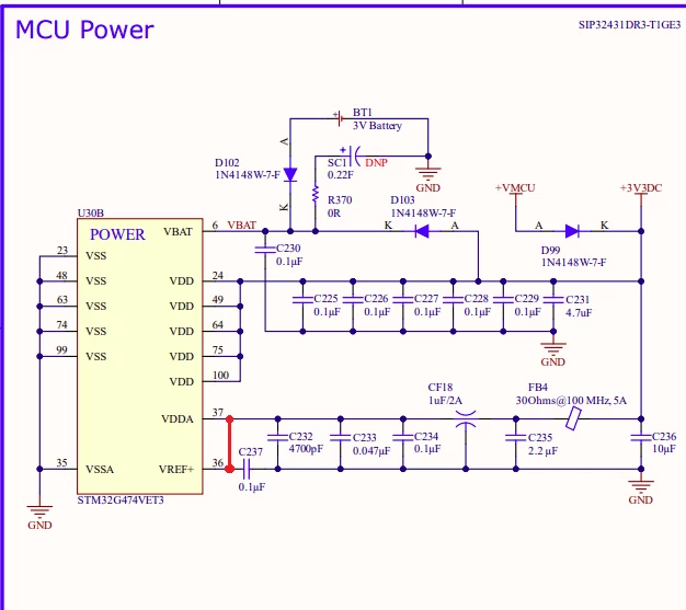
MCU-pwr.PNG

I think if you update this circuit by connection VREF+ also to 3V3 as VDDA, ADC will work correctly. 

To give better visibility on the answered topics, please click on Accept as Solution on the reply which solved your issue or answered your question.

25 replies

ST Employee
May 7, 2025 7:52 AM UTC

Hello,

can you please share your ADC settings.

To give better visibility on the answered topics, please click on Accept as Solution on the reply which solved your issue or answered your question.
Associate III
May 7, 2025 8:17 AM UTC

Sure

ADC3_1.PNG

ADC3_2.PNG

ADC3_3.PNG


ST Employee
May 7, 2025 8:46 AM UTC

The configuration seems to me OK. Can you share also the code where is used ADC and read raw ADC value? 

Is it possible to test ADC on any unconnected MCU pin to know if there is problem in HW or in FW?

To give better visibility on the answered topics, please click on Accept as Solution on the reply which solved your issue or answered your question.
Ozone
Principal
May 7, 2025 8:07 AM UTC

If you talk about the "usual" 12-bit successive-approximation ADC most STM32 implement, notice the value.
This 4095 is the maximal possible value, so it looks like the input voltage exceeds the range.

Post the relevant init code, and details about attached circuitry and voltages applied to the ADC inputs.

Associate III
May 7, 2025 8:18 AM UTC
static void MX_ADC3_Init(void)
{

 /* USER CODE BEGIN ADC3_Init 0 */

 /* USER CODE END ADC3_Init 0 */

 ADC_MultiModeTypeDef multimode = {0};
 ADC_ChannelConfTypeDef sConfig = {0};

 /* USER CODE BEGIN ADC3_Init 1 */

 /* USER CODE END ADC3_Init 1 */

 /** Common config
 */
 hadc3.Instance = ADC3;
 hadc3.Init.ClockPrescaler = ADC_CLOCK_SYNC_PCLK_DIV2;
 hadc3.Init.Resolution = ADC_RESOLUTION_12B;
 hadc3.Init.DataAlign = ADC_DATAALIGN_RIGHT;
 hadc3.Init.GainCompensation = 0;
 hadc3.Init.ScanConvMode = ADC_SCAN_DISABLE;
 hadc3.Init.EOCSelection = ADC_EOC_SINGLE_CONV;
 hadc3.Init.LowPowerAutoWait = DISABLE;
 hadc3.Init.ContinuousConvMode = DISABLE;
 hadc3.Init.NbrOfConversion = 1;
 hadc3.Init.DiscontinuousConvMode = DISABLE;
 hadc3.Init.ExternalTrigConv = ADC_SOFTWARE_START;
 hadc3.Init.ExternalTrigConvEdge = ADC_EXTERNALTRIGCONVEDGE_NONE;
 hadc3.Init.DMAContinuousRequests = DISABLE;
 hadc3.Init.Overrun = ADC_OVR_DATA_PRESERVED;
 hadc3.Init.OversamplingMode = DISABLE;
 if (HAL_ADC_Init(&hadc3) != HAL_OK)
 {
 Error_Handler();
 }

 /** Configure the ADC multi-mode
 */
 multimode.Mode = ADC_MODE_INDEPENDENT;
 if (HAL_ADCEx_MultiModeConfigChannel(&hadc3, &multimode) != HAL_OK)
 {
 Error_Handler();
 }

 /** Configure Regular Channel
 */
 sConfig.Channel = ADC_CHANNEL_10;
 sConfig.Rank = ADC_REGULAR_RANK_1;
 sConfig.SamplingTime = ADC_SAMPLETIME_2CYCLES_5;
 sConfig.SingleDiff = ADC_SINGLE_ENDED;
 sConfig.OffsetNumber = ADC_OFFSET_NONE;
 sConfig.Offset = 0;
 if (HAL_ADC_ConfigChannel(&hadc3, &sConfig) != HAL_OK)
 {
 Error_Handler();
 }
 /* USER CODE BEGIN ADC3_Init 2 */

 /* USER CODE END ADC3_Init 2 */

}
Associate III
May 7, 2025 8:21 AM UTC

ADC_sch.PNG

Andrew Neil
Super User
May 7, 2025 8:17 AM UTC

As the others have said, you need to give more details - please see How to write your question to maximize your chances to find a solution.

In particular, please post your code (see How to insert source code) & the schematics of this "custom board".

Have you checked at the STM32 pins that your ADC inputs are actually getting good signals?

Have you looked at ST's examples?

Have you tried this on a known-good ST board?


You still haven't marked the solutions to your previous threads.

A complex system that works is invariably found to have evolved from a simple system that worked.A complex system designed from scratch never works and cannot be patched up to make it work.
Ozone
Principal
May 7, 2025 9:20 AM UTC

On a related note, I remember a similiar issue with the PCF8591 IC, an (older) I2C extender IC with ADC channels.
When the input voltage at one single ADC pin on this IC exceeded Vref, all the ADC channels returned max. value.

Not sure if this applies to this case, but analog MCU inputs are not 5V tolerant. And discharge currents through protective diodes on such inputs definitely affect ADC operation.

TDK
May 7, 2025 12:40 PM UTC

Sounds like VREF+ might not be connected. 18 replies in this thread and still no schematic that includes this pin.

"If you feel a post has answered your question, please click ""Accept as Solution""."
Associate III
May 7, 2025 12:57 PM UTC


MCU-pwr.PNG

I am providing +3V3DC to analog pin for Vref based on datasheet its and output pin.  

TDK
May 7, 2025 1:36 PM UTC

VREF+ needs to be powered. Connect it to VDDA.

"If you feel a post has answered your question, please click ""Accept as Solution""."