

How to implement the USB Device CDC (VCOM) in STM32 using the Azure USBX package
- October 26, 2023
- 26 replies
- 31741 views
Summary
This article presents a tutorial on how to implement the USB Device CDC in the STM32 using the Azure USBX package. Azure USBX is an RTOS USB embedded stack developed by Microsoft® that offers a wide range of classes to be implemented both for host and device applications.
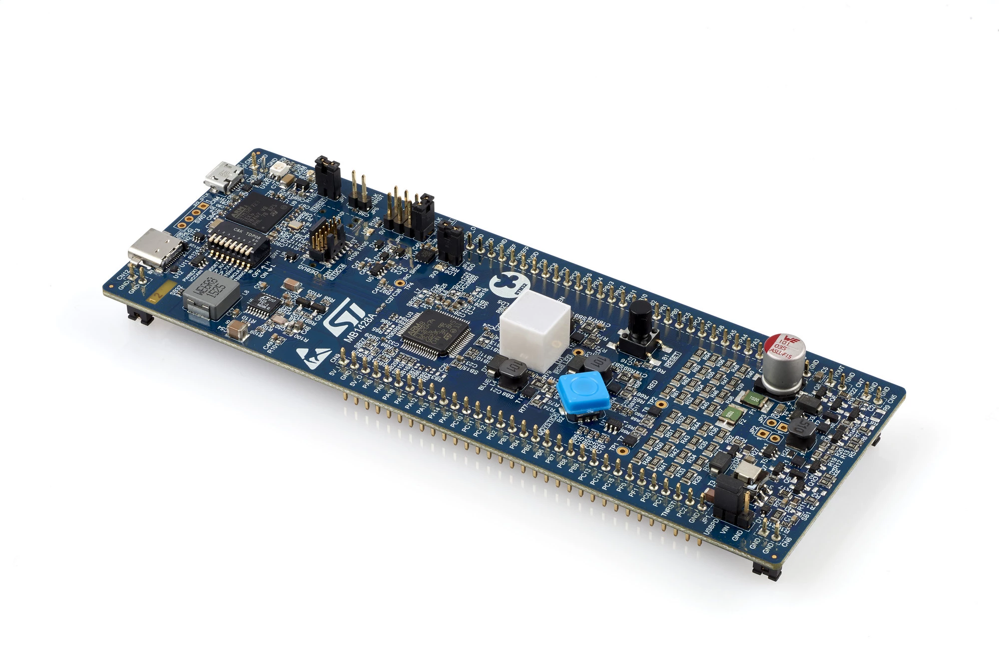
For this tutorial, we use the B-G474E-DPOW1 board, which has a USB Type-C® connector interface. However, the demonstration does not use the USB Type-C® additional features. This board has an STM32G474RET6 microcontroller, and the steps shown here can be easily adapted to any other STM32Gx family. For other families, we will present the necessary changes in the development of this article. The STM32CubeIDE 1.13.1, STM32CubeG4 1.5.1, and the X-CUBE-AZRTOS-G4 2.0.0 releases were used to build this tutorial.
1. Development
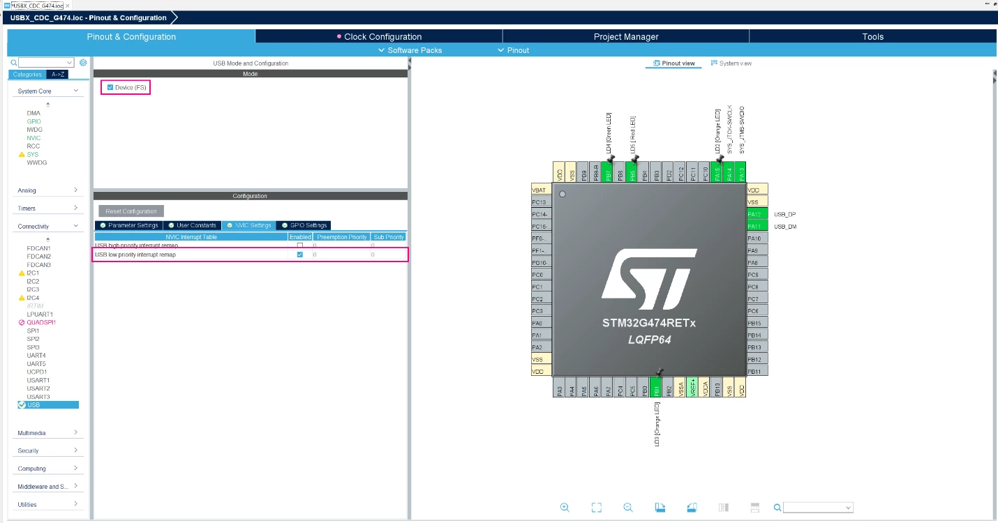
Let us start creating a project for the STM32G474RET6 in the STM32CubeIDE and enabling the PA15 (LD2 Blue LED), PB1 (LD3 Orange LED), PB7 (LD4 Green LED) and PB5 (LD5 Red LED) as GPIO Output Push-Pull to get access to the LEDs available on the board.
In the next step, we need to enable the USB Peripheral in Device (FS) mode. For this tutorial, the default Parameter Settings are used. We just need to enable the USB low-priority interrupt remap. The high priority interrupt will not work with the Azure ThreadX since it blocks the kernel to run due to the high priority interrupt.
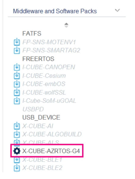
Now, navigate until the X-CUBE-AZRTOS-G4 under the Middleware and Software Packs.
Once clicked on the package, the Software Packs Component Selector menu is opened. There we need to enable the following packs:
- RTOS ThreadX -> ThreadX -> Core
- USB USBX -> USBX -> CoreSystem
- USB USBX -> USBX -> UX Device CoreStack
- USB USBX -> USBX -> UX Device Controllers
- USB USBX -> USBX -> UX Device
After that, press OK.
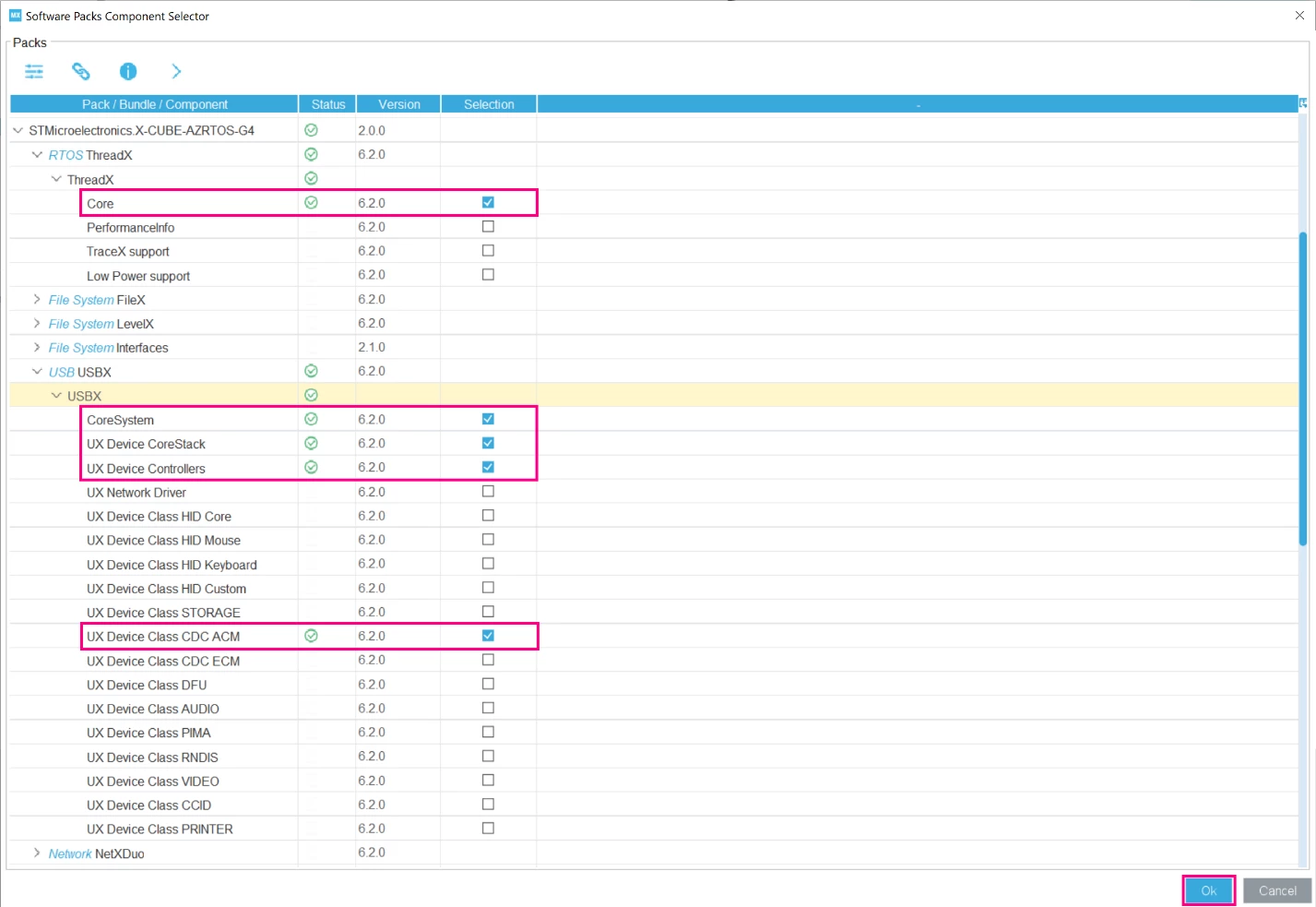
We enabled the RTOS ThreadX since the USBX was developed to run with the Azure RTOS. It is possible to run the firmware in standalone mode, but we will cover this in another article.
To use the USBX we enabled the CoreSystem and UX Device CoreStack, which contains the middle layer firmware for the USB in device mode that ensures the USB stack processing and the interface between the low and high layers. The UX Device Controllers, low layer firmware to interface with the hardware USB peripheral. And finally, the UX Device Class CDC ACM, the higher layer which includes the class components.
Going back to the STM32CubeIDE, open the X-CUBE-AZRTOS-G4 and enable both RTOS ThreadX and USB USBX. Then increase the amount of memory allocated for the USBX Device System Stack Size and USBX Device memory pool size.
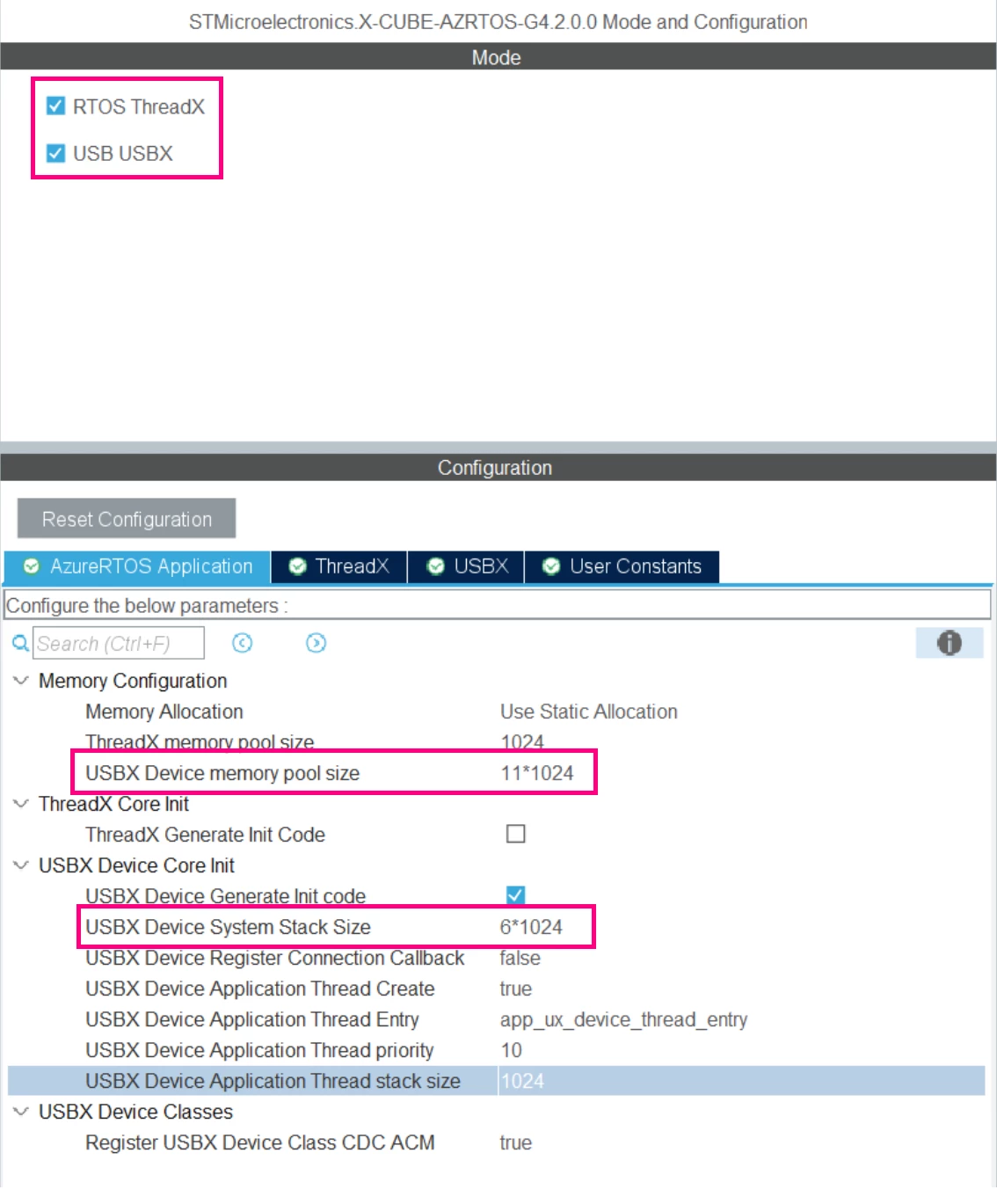
To define the amount of memory for the USBX Device System Stack Size, refer to the table below:
|
CLASS |
NEEDED MEMORY |
TOTAL |
|
HID |
4 * 1024 |
4 KB |
|
MASS STORAGE |
5 * 1024 |
5 KB |
|
DFU |
4 * 1024 |
4 KB |
|
CDC ACM |
6 * 1024 |
6 KB |
|
CDC ECM |
34 * 1024 |
34 KB |
|
VIDEO |
6 * 1024 |
6 KB |
|
RNDIS |
34 * 1024 |
34 KB |
|
MTP |
12 * 1024 |
12 KB |
|
PRINTER |
3 * 1024 |
3 KB |
|
CCID |
8 * 1024 |
8 KB |
|
Composite |
Sum of the used classes |
|
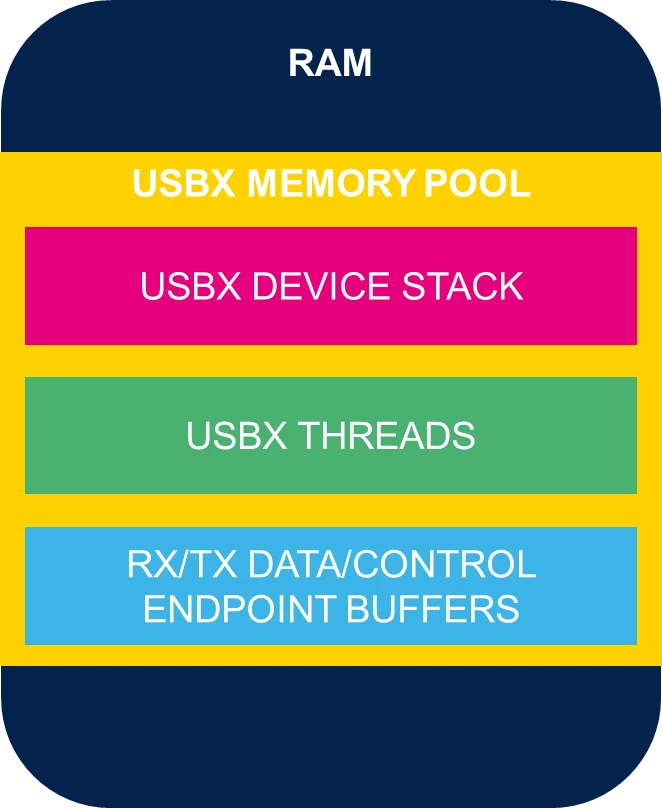
To define the amount of memory for the USBX Device memory pool size, you must take the following into account: USBX Device System Stack Size, the USBX Device Application Thread stack size, the thread stack you are planning to create for the USB application, and the RX and TX buffer.
Navigate to the USBX tab, and decrease the UX_SLAVE_REQUEST_DATA_MAX_LENGTH to save space in RAM, and change the USBD _CDCACM_ENDPOINT_IN_CMD_ADDR to 2.
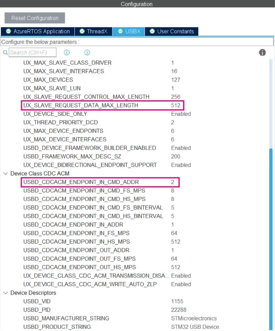
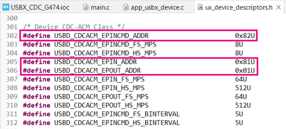
Here, we use the endpoint 0 IN/OUT as the standard control endpoint. The endpoint 1 IN/OUT for the CDC data. And finally, the endpoint 2 IN for the CDC commands. You can change these addresses as you want, just ensure to respect the USB IP capabilities.
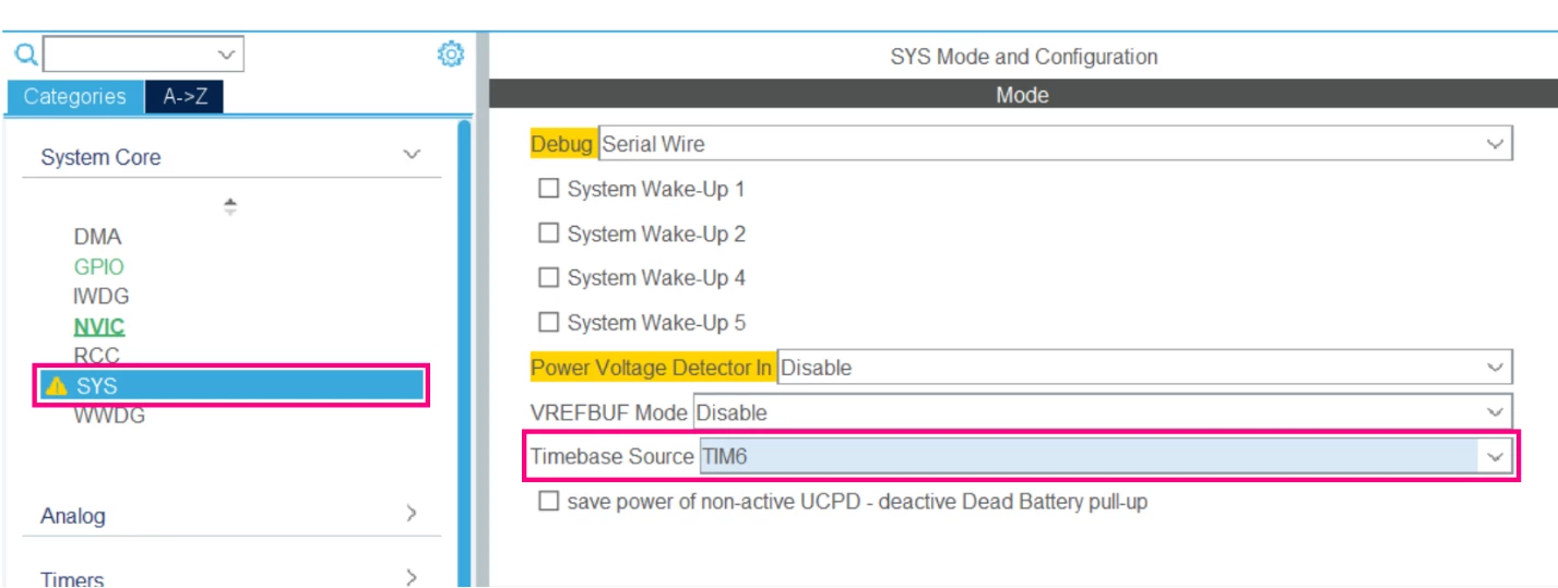
It is necessary to change the Timebase Source, since the SysTick is used the RTOS kernel. To do that, go to SYS and select a timer for the timebase.
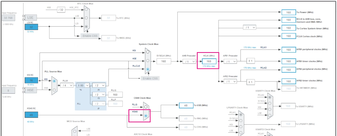
The next step in the configuration tool is to adjust the Clock Configuration. So, go to this tab, select the HSI48 for the CK48 Clock Mux source, and se the HCLK to 170MHz to extract the maximum MCU performance.
After that, navigate until Project Manager tab, then Code Generator. In this menu, enable the Generate peripheral initialization as a pair of ‘.c/.h’ files per peripheral. This helps us to get access to the USB resources.

The last step is to disable the USB Initialization in the Advanced Settings menu.
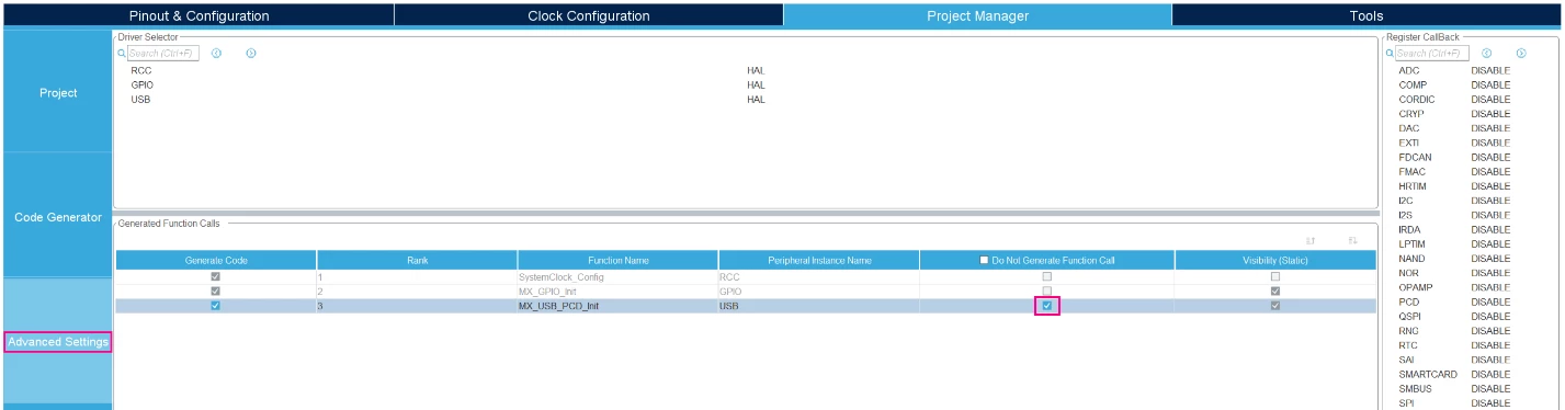
Doing that, we are all set to generate the code and start coding our application.

Once the code is generated, we have the following structure:
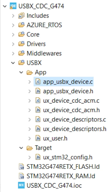
The first steps in the code development are to link the ST HAL USB driver with the USBX firmware and then initialize the USB peripheral. These steps are done in the app_usbx_device.c file. So, open that and start adding the following includes:
/* Private includes ----------------------------------------------------------*/

/* USER CODE BEGIN Includes */

#include "main.h"

#include "usb.h"

#include "ux_dcd_stm32.h"

/* USER CODE END Includes */
Then, scroll down until the app_ux_device_thread_entry function. Into this function, add the code to link the driver and initialize the USB peripheral.
static VOID app_ux_device_thread_entry(ULONG thread_input)
{
 /* USER CODE BEGIN app_ux_device_thread_entry */
 MX_USB_PCD_Init();
 HAL_PCDEx_PMAConfig(&hpcd_USB_FS, 0x00 , PCD_SNG_BUF, 0x40);
 HAL_PCDEx_PMAConfig(&hpcd_USB_FS, 0x80 , PCD_SNG_BUF, 0x80);
 HAL_PCDEx_PMAConfig(&hpcd_USB_FS, 0x01, PCD_SNG_BUF, 0xC0);
 HAL_PCDEx_PMAConfig(&hpcd_USB_FS, 0x81, PCD_SNG_BUF, 0x100);
 HAL_PCDEx_PMAConfig(&hpcd_USB_FS, 0x82, PCD_SNG_BUF, 0x140);
 ux_dcd_stm32_initialize((ULONG)USB, (ULONG)&hpcd_USB_FS);
 HAL_PCD_Start(&hpcd_USB_FS);
 /* USER CODE END app_ux_device_thread_entry */
}
The code above starts calling the MX_USB_PCD_Init() to initialize the USB peripheral.
Then the HAL_PCDEx_PMAConfig(…) function is called 5 times. This function configures the PMA (packet memory area) within the dedicated USB RAM memory for the STM32Gx families. It should be done for every endpoint used in the application. In this case for the endpoints 0 IN/OUT (0x00 and 0x80), 1 IN/OUT (0x01, 0x81) and 2 IN (0x82). The PCD_SNG_BUF parameter means that we use a single buffer for the endpoint, this is necessary since we are using the endpoint in bidirectional mode. Finally, the last parameter of this function is the PMA address, which should be selected according to the following table:
|
REGION NAME |
MEMORY ADDRESS |
SIZE |
|
BTABLE |
0x00 |
64 B |
|
TX Ep 0 Buffer |
0x40 |
64 B |
|
RX Ep 0 Buffer |
0x80 |
64 B |
|
TX Ep 1 Buffer |
0xC0 |
64 B |
|
RX Ep 1 Buffer |
0x100 |
64 B |
|
RX Ep 2 Buffer |
0x140 |
64 B |
As you may have noticed, we used the first address of the memory to store the BTABLE, which is a list of addresses of the endpoint buffers. The BTABLE stores 8 bytes for each endpoint. Since the STM32G474 has 8 endpoints, it can consume at maximum of 64 bytes.
In this example, we are using the endpoints from 0 until 2, so the rest of the table is not used. We could decrease the offset of the TX Ep 0 Buffer, optimizing the usage of the memory. However, following this table you can allocate all the 8 endpoints buffers without problems. For further details, refer to section 45.5 from the STM32G474 Reference Manual.
The next function called is ux_dcd_stm32_initialize(…) which is responsible to link the HAL USB drivers to the USBX application. And finally, we call the HAL_PCD_Start(..) to start the USB PCD peripheral.
The steps for filling this function may differ depending on the MCU family you are using. In this case, we recommend you to refer to the USBX examples available in the X-CUBE-AZRTOS-XX package, to see the correct way to set up your USB peripheral.
The endpoint addresses are defined according to the selected address in the graphical configuration tool, as presented before. To verify the generated addresses, you can double check the addresses in the ux_device_descriptors.h.
The last step is to open the ux_device_cdc_acm.c file and include the main.h header:
/* Private includes ----------------------------------------------------------*/
/* USER CODE BEGIN Includes */
#include "main.h"
/* USER CODE END Includes */
Then create the following variable:
/* Private variables ---------------------------------------------------------*/
/* USER CODE BEGIN PV */
UX_SLAVE_CLASS_CDC_ACM *cdc_acm;
/* USER CODE END PV */
Populate the activate function as follows:
VOID USBD_CDC_ACM_Activate(VOID *cdc_acm_instance)
{
 /* USER CODE BEGIN USBD_CDC_ACM_Activate */
 /* Save the instance */
 cdc_acm = (UX_SLAVE_CLASS_CDC_ACM *)cdc_acm_instance;
 /* USER CODE END USBD_CDC_ACM_Activate */
 return;
}
Doing that, we already have our USB application functional. To class resources are available in the ux_device_cdc_acm.c file. The next steps will cover a usage example of the USBX CDC class.
Let us go back to the app_usbx_device.c, in the last user code section of the MX_USBX_Device_Init(…) function and create two threads for handling the write and read features.
/* USER CODE BEGIN MX_USBX_Device_Init1 */
/* Allocate memory for the UX RX thread */
tx_byte_allocate(byte_pool, (VOID **)&pointer, 1024, TX_NO_WAIT);
/* Create the UX RX thread */
tx_thread_create(&ux_cdc_read_thread, "cdc_acm_read_usbx_app_thread_entry", usbx_cdc_acm_read_thread_entry, 1, pointer, 1024, 20, 20, TX_NO_TIME_SLICE, TX_AUTO_START);
/* Allocate memory for the UX TX thread */
tx_byte_allocate(byte_pool, (VOID **)&pointer, 1024, TX_NO_WAIT);
/* Create the UX TX thread */
tx_thread_create(&ux_cdc_write_thread, "cdc_acm_write_usbx_app_thread_entry", usbx_cdc_acm_write_thread_entry, 1, pointer, 1025, 20, 20, TX_NO_TIME_SLICE, TX_AUTO_START);
/* USER CODE END MX_USBX_Device_Init1 */
Create the threads in the private variables section:
/* USER CODE BEGIN PV */
static TX_THREAD ux_cdc_read_thread;
static TX_THREAD ux_cdc_write_thread;
/* USER CODE END PV */
Finally, add the include of the ux_device_cdc_acm.h file in the app_usbx_device.c:
/* Private includes ----------------------------------------------------------*/
/* USER CODE BEGIN Includes */
#include "main.h"
#include "usb.h"
#include "ux_dcd_stm32.h"
#include "ux_device_cdc_acm.h"
/* USER CODE END Includes */
Now, open the ux_device_cdc_acm.h and add the thread prototypes:
/* USER CODE BEGIN EFP */
VOID usbx_cdc_acm_write_thread_entry(ULONG thread_input);
VOID usbx_cdc_acm_read_thread_entry(ULONG thread_input);
/* USER CODE END EFP */
The last modifications are done to the ux_device_cdc_acm.c file, where we add the thread codes:
/* USER CODE BEGIN 1 */
VOID usbx_cdc_acm_write_thread_entry(ULONG thread_input)
{
 /* Private Variables */
 ULONG tx_actual_length;
 const uint8_t message[] = "USBX Application Running!\r\n";
 while(1)
 {
 ux_device_class_cdc_acm_write(cdc_acm, (UCHAR *)(message), sizeof(message), &tx_actual_length);
 tx_thread_sleep(100);
 }
}

VOID usbx_cdc_acm_read_thread_entry(ULONG thread_input)
{
 /* Private Variables */
 ULONG rx_actual_length;
 uint8_t UserRxBuffer[64];
 /* Infinite Loop */
 while(1)
 {
 if(cdc_acm != UX_NULL)
 {
 ux_device_class_cdc_acm_read(cdc_acm, (UCHAR *)UserRxBuffer, 64, &rx_actual_length);
 switch(UserRxBuffer[rx_actual_length-1])
 {
 case '1':
 HAL_GPIO_WritePin(LD3_GPIO_Port, LD3_Pin, GPIO_PIN_SET);
 break;
 case '0':
 HAL_GPIO_WritePin(LD3_GPIO_Port, LD3_Pin, GPIO_PIN_RESET);
 break;
 }
 }
 }
}

/* USER CODE END 1 */
And that concludes our example code. Connect the USB of the STLINK in your board, then the USB Type-C®, start a debug session and see the application running!
2. Results
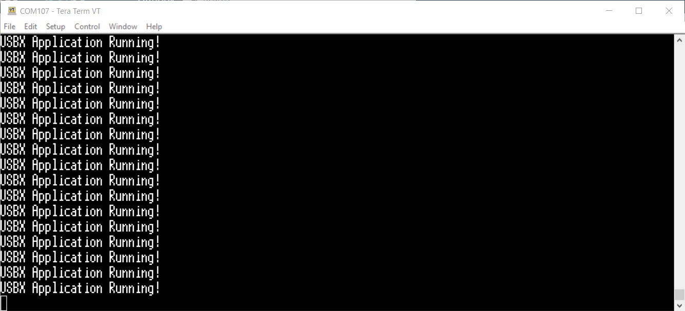
Once you have opened the debug session, let the code run and open a virtual COM port terminal in your computer. The “USBX Application Running!” message should be printed on every second. If you send the character ‘1’ the Orange LED should be turned ON, and it should be turned OFF when the character ‘0’ is sent.
3. Conclusion
That concludes our article. Now you have the needed information to start developing with the USBX Device stack. The steps for implementing other classes are similar up to the class layer code. In these cases, our GitHub contains a vast set of demonstration projects that includes most of the available classes both for Host and Device applications.
Our best wishes for your projects, and we hope you enjoyed the material!
Useful links
Here are some useful links for you that is developing with the USBX package:
STMicroelectronics GitHub - X-CUBE-AZRTOS-G4
STMicroelectronics - Azure(R) RTOS Middleware
Microsoft Azure RTOS documentation hub | Microsoft Learn
Understand Azure RTOS USBX | Microsoft Learn
B-G474E-DPOW1 - Discovery kit with STM32G474RE MCU - STMicroelectronics
