


How to implement a webserver in STM32 using NetXDuo Ethernet middleware
- 35 replies
- 63555 views
This article demonstrates how to implement a webserver application using the AzureRTOS ecosystem, relying on the NetXDuo stack for Ethernet communication. We also use FileX for hosting the pages in the MCU’s embedded flash and ThreadX as RTOS. The demo uses the NUCLEO-H753ZI board but can be easily tailored to a different STM32.
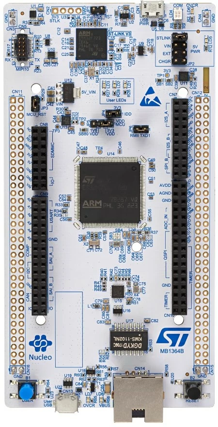 Figure 1 – STM32 Nucleo-H753ZI
Introduction
A web page is a useful resource for several types of applications. It allows the user to communicate with a device nearly instantly and as far as their network can go.
The web pages are going to be completely hosted inside the microcontroller’s flash, which includes the HTML files as well as all the scripts and images. To facilitate the memory management, LevelX and FileX stacks are used. FileX is responsible for hosting a simple file system inside the flash configured by LevelX to be a simulated NOR driver with a 1 MB capacity.
The NetXDuo is responsible for managing all internet protocols required for this application to work: HTTP server, TCP/IP, DHCP, ICMP, ARP, UDP, and IP. Ethernet and MAC protocols are being managed at the hardware level hardware.
To allocate the web pages as a binary file inside the microcontroller, a tool called fxImageCreator is used, the tool and the software license agreement are attached, please make sure to read the license agreement before using it. The tool creates a bin image with a file system for embedded system memory, containing the structure file tree and identifying the file easily. While it can be used with external memories, it works nicely with embedded memory as this tool can be configured to fill the exact number of bytes made available by the LevelX setting.
The web_demo.bin file is provided in this article, containing all files required for three html pages to be displayed and interacted with. Just as a quick reference, the file about.html is a page displaying a few product features present in the NUCLEO-H753, including an image of the board. A small debrief about the demo is also shown, together with links to the Nucleo board online page and the two other pages hosted by the demo, called Index.html.
Index.html displays further information about the Nucleo board and its microcontroller with images and links. Furthermore, a description of the Azure RTOS STM32Cube expansion and dashboard.html that displays system performance data regarding RTOS TCP traffic and connection information. Two graphs are shown representing the number of times each thread ran and how many NetXDuo packets are available. A toggle button at the bottom of the page controls the green LED on the board.
1. Development
To start the application, we first need to create a project in STM32CubeIDE using the NUCLEO-H753ZI board. After setting a project name press “no” to the pop-up message about starting the peripherals in default mode, as the article will cover all needed settings.
1.1 System core tab setup
One of the key aspects is properly configuring the MPU on the CORTEX_M7. Enable both CPU caches, speculation default mode and set the MPU control mode as background region privileged access only + MPU disabled during hard fault, NMI, and FAUTMASK handlers. More details about the settings and addresses are covered in this article: https://community.st.com/t5/stm32-mcus/how-to-create-project-for-stm32h7-with-ethernet-and-lwip-stack/ta-p/49308
MPU regions must be configured to specify the access to both Ethernet descriptors, such as in the picture below.
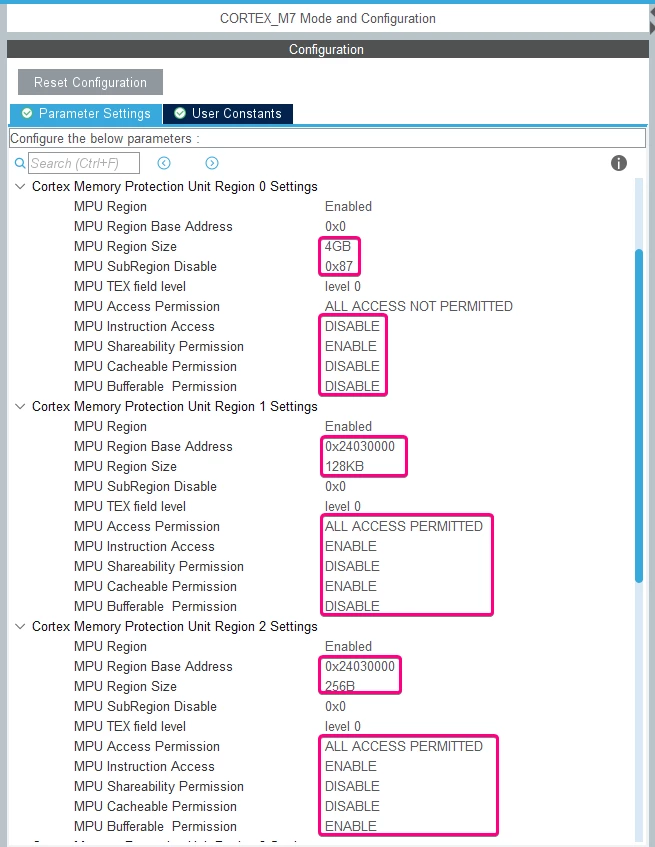 Figure 2 – MPU configuration
To allow for optimal performance the microcontroller should run at its highest frequency. As stated in the errata sheet ES0392 revisions Y or W of the H753 family are limited to run at 400 MHz and does not require this step. However, if revision X or V is being used, the RCC tab must be configured.
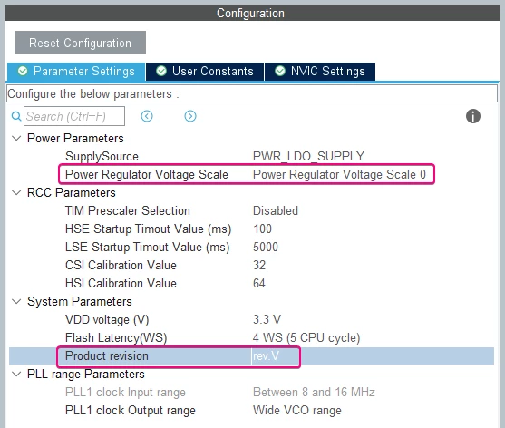 Figure 3 – RCC configuration
Setting the product revision to V allows the user to configure the power regulator voltage scale to 0, which enables the microcontroller to reach its highest possible frequency.
Next in the SYS section, the timebase source must be set to a timer, since SysTick is used by the RTOS. Timers 6 or 7 are recommended since they are basic timers with no external signal capabilities.
 Figure 4 – Timebase source configuration
1.1.1 Connectivity tab setup
In the connectivity tab, both the Ethernet and USART3 peripherals are used. Ethernet is the focus of this application, and the serial port is used for debug purposes, such as application flow and IP address handling.
RMII Ethernet mode must be enabled. Configure the Rx buffers length to the maximum value and the first descriptor addresses must be set as such:
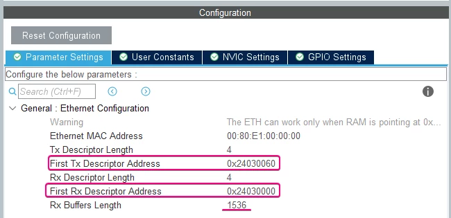 Figure 5 – Ethernet configuration
Lastly in the Ethernet tab, navigate to the NVIC settings tab and check the Ethernet global interrupt enable box.
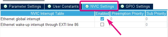 Figure 6 – Ethernet NVIC configuration
The USART3 peripheral pins are mapped in the pinout view as STLINK_TX and STLINK_RX, as they are configured as the virtual COM port. Configure the peripheral in asynchronous mode and the desired baud rate, word length, parity, and stop bits parameters. The default settings are:
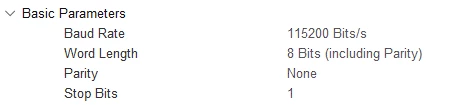 Figure 7 – USART3 configuration
1.1.2 Middleware and software packs tab setup
In this tab, "MIDDLEWARES" is selected. Look for the X-CUBE-AZRTOS-H7 and download its latest version if it is greyed out. Once it is installed click it to open the software packs component selector pop-up.
Now, select the following middleware to configure the operational system ThreadX, the file system FileX and its subsystem LevelX. Doing so, we can simulate a NOR interface inside the microcontroller’s memory:
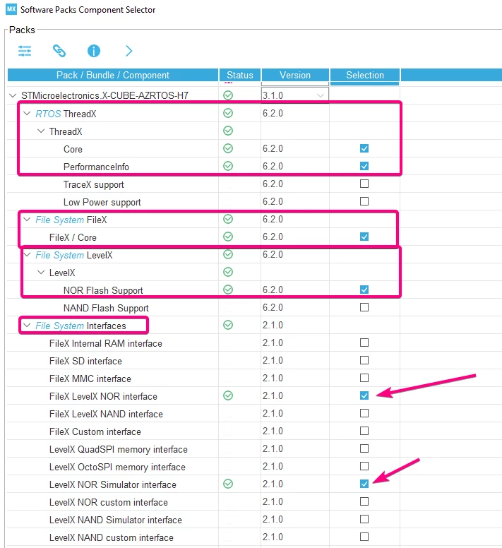 Figure 8 – Software Packs ecosystem configuration
Next, the network middleware and interface must be configured. NetXDuo has its core and both DHCP client and web server addons enabled. The network interfaces and BSP PHY must be configured respecting the parts present in the Nucleo board.
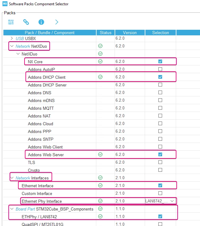 Figure 9 – Software Packs network configuration
After selecting all the necessary components, press ok and the pop-up will be closed to present a few checkboxes. All of them must be checked so that the middleware is included in the project files.
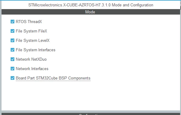 Figure 10 – Middleware selection tab
1.1.2.1 LevelX Configuration
LevelX is used in this application to simulate a NOR driver in the microcontroller’s internal memory.
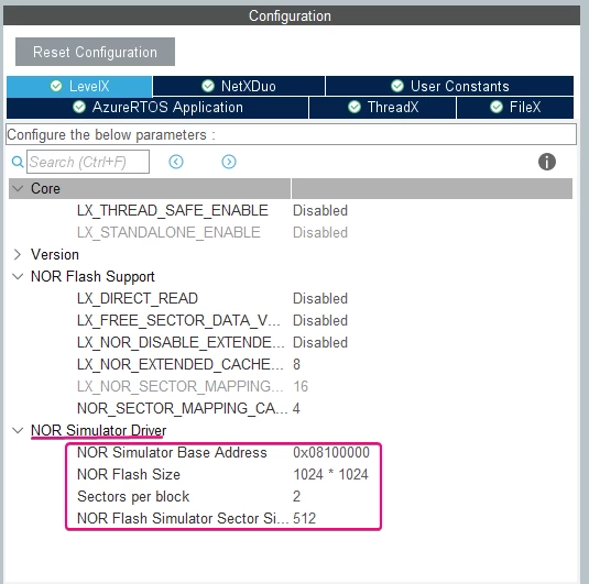 Figure 11 – LevelX Configuration
We must configure the base address of the simulated NOR driver to 0x08100000, its size to 1 MB and sectors to two, as the picture shows. The html files are stored at this address.
1.1.2.2 NetXDuo Configuration
This middleware is the heart of the application, managing the webserver and all its required protocols under the OSI model. Starting with the core, NX_ENABLE_INTERFACE_CAPABILITY must be checked.
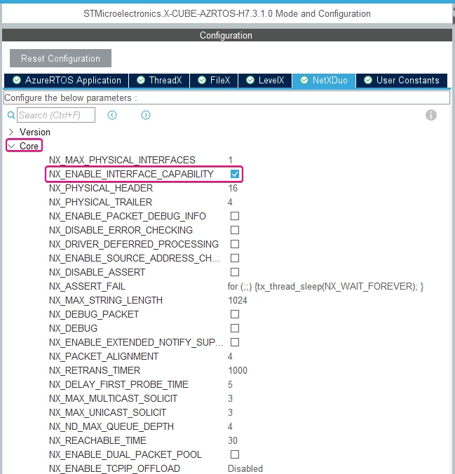 Figure 12 – NetXDuo configuration
On the IP subsection, the NX_DISABLE_IPV6 checkbox must be ticked and the other parameters as default
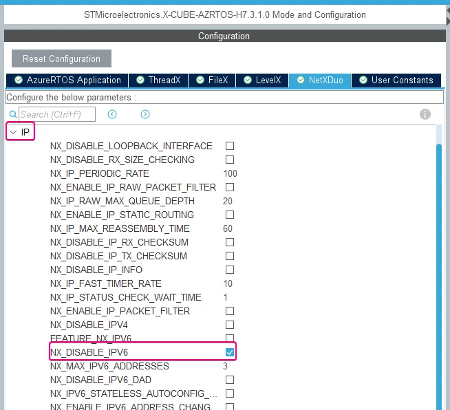 Figure 13 – IP configuration
All other NetXDuo tabs should be kept at their default settings.
1.1.2.3 AzureRTOS Application Configuration
This tab configures the memory allocation and initialization of all related stacks and middlewares.
The NetXDuo memory pool size must be multiplied by 100. "FileX Generate Init Code" box must be unchecked. NetXDuo pool size in number of packets must be set to 50 instead of 5. The IP instance thread size multiplied by 2. The last configuration is to check the "Initialize DHCP protocol."
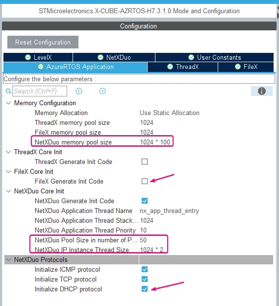 Figure 14 – Pool size configuration
1.1.2.4 ThreadX Configuration
Here is where the kernel is configured. The only difference from default settings is that the TX_THREAD_ENABLE_PERFORMANCE_INFO parameter must be enabled.
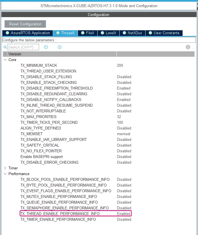 Figure 15 – ThreadX configuration
After enabling the RTOS, the preemption priority of the Ethernet interruption must be configured to 7. This is done in the NVIC tab as shown below:
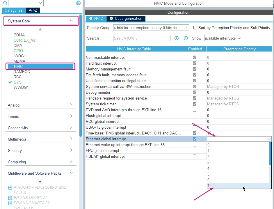 Figure 16 – NVIC configuration
The FileX tab configures several parameters related to the file system, but for this application it must be set to its default settings.
1.1.4 Debug tab setup
In this tab, the "Serial Wire" debug mode must be configured. This adds two signals to the pinout view, both connected to STLINK on the Nucleo board allowing the use of debug features.
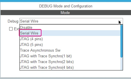 Figure 17 – Debug configuration
1.1.5 Clock Configuration
As briefly mentioned earlier, to achieve the best possible performance the M7 core must run at the highest frequency allowed. To do so, the SYSCLK source must be set to PLLCLK and the PLL1 block must have its values configured to multiply the 64 MHz HSI clock to 480 MHz. This is given that the hardware revision is rev. V or X, otherwise the maximum frequency allowed is 400 MHz (ES0392). The STM32CubeIDE calculates the values automatically if the desired clock frequency is inserted in any of the blue contoured blocks.
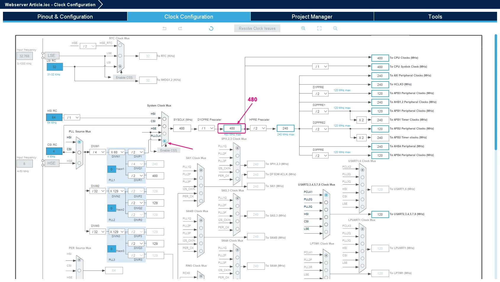 Figure 18 – Clock configuration
Once all this setup is completed in the device configuration tool perspective, the code snippet must be generated using the Alt + K shortcut. This should save and configure the project file tree and open main.c.
1.2 Coding the project
Now, the project has all its foundation configured and set for the code to be constructed. Several files are modified in the project to create our web server application, including: main.c, app_azure_rtos.c, app_filex.c, app_netxduo.c, and STM32H753ZITX_FLASH.ld.
1.2.1 main.c
To allow for easier debugging and communication with the VCOM, the printf function must be configured. The following code must be inserted in the USER CODE BEGIN PFP section.
int __io_putchar(int ch) {
 /* Place your implementation of fputc here */
 /* e.g. write a character to the USART3 and Loop until the end of transmission */
 HAL_UART_Transmit(&huart3, (uint8_t*) &ch, 1, 0xFFFF);
 return ch;
}
Also to provide better debugging and code handling, the default Error_Handler() function must be modified. Adding LED toggling functionality allows for visual identification that an error has happened, making the troubleshooting process faster and easier, if needed. The error handler function is defined around line 460 of the code and should look like this
void Error_Handler(void)
{
 /* USER CODE BEGIN Error_Handler_Debug */
 /* User can add his own implementation to report the HAL error return state */
 HAL_GPIO_WritePin(LD1_GPIO_Port, LD1_Pin, GPIO_PIN_RESET);
 while (1)
 {
 HAL_GPIO_TogglePin(LD2_GPIO_Port, LD2_Pin);
 HAL_Delay(200);
 }
 /* USER CODE END Error_Handler_Debug */
}
With this code the green LED turns off, all IRQ interruptions are disabled, and the red LED starts blinking indefinitely.
1.2.2 app_azure_rtos.c
This file has several memory allocation calls, and if any of them fail the application will not function. To improve the debugging capabilities, we recommend that the error sections should call the Error_Handler function. The following is an example of that.
if (tx_byte_pool_create(&tx_app_byte_pool, "Tx App memory pool", tx_byte_pool_buffer, TX_APP_MEM_POOL_SIZE) != TX_SUCCESS)
{
	/* USER CODE BEGIN TX_Byte_Pool_Error */
	Error_Handler();
	/* USER CODE END TX_Byte_Pool_Error */
}
else
{
	/* USER CODE BEGIN TX_Byte_Pool_Success */

	/* USER CODE END TX_Byte_Pool_Success */

	memory_ptr = (VOID *)&tx_app_byte_pool;
	status = App_ThreadX_Init(memory_ptr);
	if (status != TX_SUCCESS)
	{
		/* USER CODE BEGIN App_ThreadX_Init_Error */
		Error_Handler();
		/* USER CODE END App_ThreadX_Init_Error */
	}

	/* USER CODE BEGIN App_ThreadX_Init_Success */

	/* USER CODE END App_ThreadX_Init_Success */

}
1.2.3 app_filex.c
A single line of code must be added to this file, and it is responsible for allocating the file system memory pool.
 /* USER CODE BEGIN MX_FileX_MEM_POOL */
 (void)byte_pool;
 /* USER CODE END MX_FileX_MEM_POOL */
1.2.4 app_netxduo.c
This file holds most of the coding for this application, as it manages all protocols used to have a webserver functional. First, a few header files must be included
/* USER CODE BEGIN Includes */
#include "main.h"
#include "nx_web_http_server.h"
#include "app_filex.h"
/* USER CODE END Includes */
Afterwards, private variables must be created to set data structures essential for ThreadX, NetXDuo byte pools, and the FileX data structures.
/* Define Threadx global data structures. */
TX_THREAD AppServerThread;
TX_THREAD LedThread;
TX_THREAD AppLinkThread;

/* Led toggling thread entry */
void LedThread_Entry(ULONG thread_input);

/* Define NetX global data structures. */

NX_PACKET_POOL WebServerPool;

ULONG IpAddress;
ULONG NetMask;
ULONG free_bytes;

NX_WEB_HTTP_SERVER HTTPServer;

/* Set nx_server_pool start address */
#if defined ( __ICCARM__ ) /* IAR Compiler */
#pragma location = ".NxServerPoolSection"
#elif defined ( __CC_ARM ) || defined(__ARMCC_VERSION) /* ARM Compiler 5/6 */
__attribute__((section(".NxServerPoolSection")))
#elif defined ( __GNUC__ ) /* GNU Compiler */
__attribute__((section(".NxServerPoolSection")))
#endif
static uint8_t nx_server_pool[SERVER_POOL_SIZE];

/* Define FileX global data structures. */

/* the server reads the content from the uSD, a FX_MEDIA instance is required */
FX_MEDIA Flash_Media;

/* Buffer for FileX FX_MEDIA sector cache. this should be 32-Bytes aligned to avoid
 cache maintenance issues */
ALIGN_32BYTES (uint32_t DataBuffer[512]);
In the next user code portion, the private function prototypes must be added. Three thread prototypes are added, as follows:
/* USER CODE BEGIN PFP */

/* HTTP server thread entry */
static void nx_server_thread_entry(ULONG thread_input);
static VOID App_Link_Thread_Entry(ULONG thread_input);

/* Server callback when a new request from a client is triggered */
static UINT webserver_request_notify_callback(NX_WEB_HTTP_SERVER *server_ptr, UINT request_type, CHAR *resource, NX_PACKET *packet_ptr);
/* USER CODE END PFP */
The next portion of code to be modified is USER CODE BEGIN MX_NetXDuo_Init
printf("Nx_Webserver application started..\n");

/* Initialize the NetXDuo system. */
nx_system_initialize();


/* Allocate the server packet pool. */
ret = tx_byte_allocate(byte_pool, (VOID **) &pointer, SERVER_POOL_SIZE, TX_NO_WAIT);

/* Check server packet pool memory allocation. */
if (ret != NX_SUCCESS)
{
	printf("Packet pool memory allocation failed : 0x%02x\n", ret);
	Error_Handler();
}

/* Create the server packet pool. */
ret = nx_packet_pool_create(&WebServerPool, "HTTP Server Packet Pool", SERVER_PACKET_SIZE, nx_server_pool, SERVER_POOL_SIZE);

/* Check for server pool creation status. */
if (ret != NX_SUCCESS)
{
	printf("Server pool creation failed : 0x%02x\n", ret);
	Error_Handler();
}

/* Allocate the server stack. */
ret = tx_byte_allocate(byte_pool, (VOID **) &pointer, SERVER_STACK, TX_NO_WAIT);

/* Check server stack memory allocation. */
if (ret != NX_SUCCESS)
{
	printf("Server stack memory allocation failed : 0x%02x\n", ret);
	Error_Handler();
}
Here some memory handling takes place: Server packet pool and server stack are allocated, and their allocation is checked. If it fails, a debug message is displayed and the error handler function called. Most threads and functions from now on will have this error checking functionality.
The next step is to allocate memory and create threads for all services going to be used. HTTP server, web server thread, a thread to blink the LED, and a link thread are all created in this portion, also memory allocation for all these services and the TCP server thread.
/* Create the HTTP Server. */
ret = nx_web_http_server_create(&HTTPServer, "WEB HTTP Server", &NetXDuoEthIpInstance, CONNECTION_PORT,&Flash_Media, pointer,
 SERVER_STACK, &WebServerPool, NX_NULL, webserver_request_notify_callback);

if (ret != NX_SUCCESS)
{
 printf("HTTP Server creation failed: 0x%02x\n", ret);
 Error_Handler();
}

/* Allocate the TCP server thread stack. */
ret = tx_byte_allocate(byte_pool, (VOID **) &pointer, 2 * DEFAULT_MEMORY_SIZE, TX_NO_WAIT);

/* Check server thread memory allocation. */
if (ret != NX_SUCCESS)
{
 printf("Server thread memory allocation failed : 0x%02x\n", ret);
 Error_Handler();
}

/* create the web server thread */
ret = tx_thread_create(&AppServerThread, "App Server Thread", nx_server_thread_entry, 0, pointer, 2 * DEFAULT_MEMORY_SIZE,
 DEFAULT_PRIORITY, DEFAULT_PRIORITY, TX_NO_TIME_SLICE, TX_DONT_START);

if (ret != TX_SUCCESS)
{
 return NX_NOT_ENABLED;
}

 /* Allocate the memory for toggle green led thread */
if (tx_byte_allocate(byte_pool, (VOID **) &pointer, DEFAULT_MEMORY_SIZE, TX_NO_WAIT) != TX_SUCCESS)
{
 return TX_POOL_ERROR;
}

/* create the LED control thread */
ret = tx_thread_create(&LedThread, "LED control Thread", LedThread_Entry, 0, pointer, DEFAULT_MEMORY_SIZE,
 TOGGLE_LED_PRIORITY, TOGGLE_LED_PRIORITY, TX_NO_TIME_SLICE, TX_DONT_START);

if (ret != TX_SUCCESS)
{
 return NX_NOT_ENABLED;
}

/* Allocate the memory for Link thread */
if (tx_byte_allocate(byte_pool, (VOID **) &pointer,2 * DEFAULT_MEMORY_SIZE, TX_NO_WAIT) != TX_SUCCESS)
{
 return TX_POOL_ERROR;
}

/* create the Link thread */
ret = tx_thread_create(&AppLinkThread, "App Link Thread", App_Link_Thread_Entry, 0, pointer, 2 * DEFAULT_MEMORY_SIZE,
 LINK_PRIORITY, LINK_PRIORITY, TX_NO_TIME_SLICE, TX_AUTO_START);

if (ret != TX_SUCCESS)
{
 return NX_NOT_ENABLED;
}
With this, the user code MX_NetXDuo_Init is complete, moving on to the nx_app_thread_entry function. Error handling features must be added to the error user code sections.
 /* USER CODE BEGIN IP address change callback error */
 /* Error, call error handler.*/
 Error_Handler();
 /* USER CODE END IP address change callback error */
/* USER CODE BEGIN DHCP client start error */
/* Error, call error handler.*/
Error_Handler();
/* USER CODE END DHCP client start error */
/* USER CODE BEGIN DHCPSemaphore get error */
/* Error, call error handler.*/
Error_Handler();
/* USER CODE END DHCPSemaphore get error */
Lastly in this thread function, in the /* USER CODE BEGIN Nx_App_Thread_Entry 2 */, the IP address must be acquired and printed. Given that the network is correctly initialized, the web server thread resumes, and the main thread is relinquished.
/* USER CODE BEGIN Nx_App_Thread_Entry 2 */
 /* get IP address */
 ret = nx_ip_address_get(&NetXDuoEthIpInstance, &IpAddress, &NetMask);

 PRINT_IP_ADDRESS(IpAddress);

 if (ret != TX_SUCCESS)
 {
 Error_Handler();
 }

 /* the network is correctly initialized, start the WEB server thread */
 tx_thread_resume(&AppServerThread);

 /* this thread is not needed any more, we relinquish it */
 tx_thread_relinquish();
 /* USER CODE END Nx_App_Thread_Entry 2 */
Inside the /*USER CODE 1*/ section, a few threads must be created. They manage most of the application functions, such as LED blinking, server command handling, and html page opening.
The first thread to be created is a callback to handle all possible web server requests.
UINT webserver_request_notify_callback(NX_WEB_HTTP_SERVER *server_ptr, UINT request_type, CHAR *resource, NX_PACKET *packet_ptr)
{

 CHAR temp_string[30] = {'\0'};
 CHAR data[512] = {'\0'};
 UINT string_length;
 NX_PACKET *resp_packet_ptr;
 UINT status;
 ULONG resumptions;
 ULONG suspensions;
 ULONG idle_returns;
 ULONG non_idle_returns;
 ULONG total_bytes_sent;
 ULONG total_bytes_received;
 ULONG connections;
 ULONG disconnections;
 ULONG main_thread_count;
 ULONG server_thread_count;
 ULONG led_thread_count;
 CHAR *main_thread_name;
 CHAR *server_thread_name;
 CHAR *led_thread_name;

 /*
 * At each new request we toggle the green led, but in a real use case this callback can serve
 * to trigger more advanced tasks, like starting background threads or gather system info
 * and append them into the web page.
 */
 /* Get the requested data from packet */
 if (strcmp(resource, "/GetTXData") == 0)
 {
 /* Let HTTP server know the response has been sent. */
 tx_thread_performance_system_info_get(&resumptions, &suspensions, NULL, NULL, NULL, NULL, NULL, NULL, NULL, &non_idle_returns, &idle_returns);

 sprintf (data, "%lu,%lu,%lu,%lu", resumptions, suspensions, idle_returns, non_idle_returns);
 }
 else if (strcmp(resource, "/GetNXData") == 0)
 {
 nx_tcp_info_get(&NetXDuoEthIpInstance, NULL, &total_bytes_sent, NULL, &total_bytes_received, NULL, NULL, NULL, &connections, &disconnections, NULL, NULL);
 sprintf (data, "%lu,%lu,%lu,%lu",total_bytes_received, total_bytes_sent, connections, disconnections);
 }
 else if (strcmp(resource, "/GetNetInfo") == 0)
 {
 sprintf(data, "%lu.%lu.%lu.%lu,%d", (IpAddress >> 24) & 0xff, (IpAddress >> 16) & 0xff, (IpAddress >> & 0xff, IpAddress& 0xff, CONNECTION_PORT);
 }

 else if (strcmp(resource, "/GetTxCount") == 0)
 {
 tx_thread_info_get(&NxAppThread, &main_thread_name, NULL, &main_thread_count, NULL, NULL, NULL, NULL, NULL);
 tx_thread_info_get(&AppServerThread, &server_thread_name, NULL, &server_thread_count, NULL, NULL, NULL, NULL, NULL);
 tx_thread_info_get(&LedThread, &led_thread_name, NULL, &led_thread_count, NULL, NULL, NULL, NULL, NULL);
 sprintf (data, "%s,%lu ,%s,%lu,%s,%lu", main_thread_name, main_thread_count, server_thread_name, server_thread_count,led_thread_name, led_thread_count);

 }
 else if (strcmp(resource, "/GetNXPacket") == 0)
 {
 sprintf (data, "%lu", NxAppPool.nx_packet_pool_available);
 }
 else if (strcmp(resource, "/GetNXPacketlen") == 0)
 {
 sprintf (data, "%lu", (NxAppPool.nx_packet_pool_available_list)->nx_packet_length );
 }
 else if (strcmp(resource, "/LedOn") == 0)
 {
 printf(" Toggling Green Led On \n");
 tx_thread_resume(&LedThread);
 }
 else if (strcmp(resource, "/LedOff") == 0)
 {
 printf(" Toggling Green Led Off \n");
 HAL_GPIO_WritePin (LD1_GPIO_Port, LD1_Pin, GPIO_PIN_SET);
 tx_thread_suspend(&LedThread);
 }
 else
 {
 return NX_SUCCESS;
 }
 /* Derive the client request type from the client request. */
 nx_web_http_server_type_get(server_ptr, server_ptr -> nx_web_http_server_request_resource, temp_string, &string_length);

 /* Null terminate the string. */
 temp_string[string_length] = '\0';

 /* Now build a response header with server status is OK and no additional header info. */
 status = nx_web_http_server_callback_generate_response_header(server_ptr, &resp_packet_ptr, NX_WEB_HTTP_STATUS_OK,
 strlen(data), temp_string, NX_NULL);

 status = _nxe_packet_data_append(resp_packet_ptr, data, strlen(data), server_ptr->nx_web_http_server_packet_pool_ptr, NX_WAIT_FOREVER);
 /* Now send the packet! */

 status = nx_web_http_server_callback_packet_send(server_ptr, resp_packet_ptr);
 if (status != NX_SUCCESS)
 {
 nx_packet_release(resp_packet_ptr);
 return status;
 }
 return(NX_WEB_HTTP_CALLBACK_COMPLETED);
}
Web server requests come from the html page or the script under it. The resource string is the request being sent by the web server, such as LedOn. This string is programmed either in the script or the html page itself, this case being the first option.
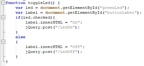 Figure 19 – Script showcase
This figure shows the script for the LED toggle slider button on the dashboard.html page provided.
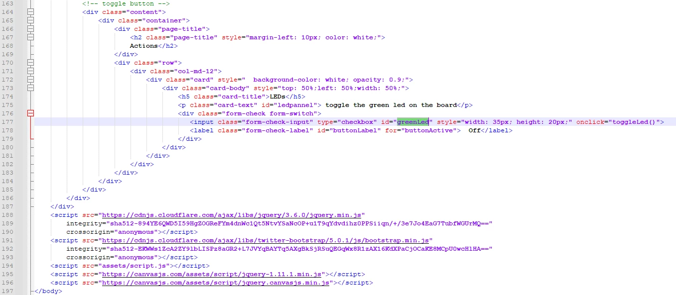 Figure 20 – Led Toggle script
This figure shows the id of the slider element toggling the LED in the web server page. It is possible to implement your own code if you edit the script for new buttons or extra display spaces. This allows you to append ADC data, PWM channel handling, and many other functionalities.
Next up, a small vector must be created to allow the application to understand exactly what type of file it is transporting to present it on the web page.
/**
* @brief Application thread for HTTP web server
* thread_input : thread input
* @retval None
*/

static NX_WEB_HTTP_SERVER_MIME_MAP app_mime_maps[] =
{
 {"css", "text/css"},
 {"svg", "image/svg+xml"},
 {"png", "image/png"},
 {"jpg", "image/jpg"}
};
The next thread is the main thread of the application, being the one responsible for opening the web server content from the LevelX nor driver and starting the HTTP server.
void nx_server_thread_entry(ULONG thread_input)
{
 /* HTTP WEB SERVER THREAD Entry */
 UINT status;
 NX_PARAMETER_NOT_USED(thread_input);

 /* Open the levelx_nor driver. */
 status = fx_media_open(&Flash_Media, "STM32_SDIO_DISK", fx_stm32_levelx_nor_driver, (VOID *)LX_NOR_SIMULATOR_DRIVER_ID, DataBuffer, sizeof(DataBuffer));

 /* Check the media opening status. */
 if (status != FX_SUCCESS)
 {
 /*Print Media Opening error. */
 printf("FX media opening failed : 0x%02x\n", status);
 /* Error, call error handler.*/
 Error_Handler();
 }
 else
 {
 /* Print Media Opening Success. */
 printf("Fx media successfully opened.\n");

 fx_media_space_available(&Flash_Media, &free_bytes);
 }

 status = nx_web_http_server_mime_maps_additional_set(&HTTPServer,&app_mime_maps[0], 4);

 /* Start the WEB HTTP Server. */
 status = nx_web_http_server_start(&HTTPServer);

 /* Check the WEB HTTP Server starting status. */
 if (status != NX_SUCCESS)
 {
 /* Print HTTP WEB Server starting error. */
 printf("HTTP WEB Server Starting Failed, error: 0x%02x\n", status);
 /* Error, call error handler.*/
 Error_Handler();
 }
 else
 {
 /* Print HTTP WEB Server Starting success. */
 printf("HTTP WEB Server successfully started.\n");
 /* LED1 On. */
 }
}
The last threads to be created are responsible for LED toggling and Ethernet cable disconnection handling.
void LedThread_Entry(ULONG thread_input)
{
 (void) thread_input;
 /* Infinite loop */
 while (1)
 {
 HAL_GPIO_TogglePin(LD1_GPIO_Port, LD1_Pin);
 /* Delay for 500ms (App_Delay is used to avoid context change). */
 tx_thread_sleep(50);
 }
}

/**
* @brief Link thread entry
* thread_input: ULONG thread parameter
* @retval none
*/
static VOID App_Link_Thread_Entry(ULONG thread_input)
{
 ULONG actual_status;
 UINT linkdown = 0, status;

 while(1)
 {
 /* Get Physical Link status. */
 status = nx_ip_interface_status_check(&NetXDuoEthIpInstance, 0, NX_IP_LINK_ENABLED,
 &actual_status, 10);

 if(status == NX_SUCCESS)
 {
 if(linkdown == 1)
 {
 linkdown = 0;
 status = nx_ip_interface_status_check(&NetXDuoEthIpInstance, 0, NX_IP_ADDRESS_RESOLVED,
 &actual_status, 10);
 if(status == NX_SUCCESS)
 {
 /* The network cable is connected again. */
 printf("The network cable is connected again.\n");
 /* Print Webserver Client is available again. */
 printf("Webserver Client is available again.\n");
 }
 else
 {
 /* The network cable is connected. */
 printf("The network cable is connected.\n");
 /* Send command to Enable Nx driver. */
 nx_ip_driver_direct_command(&NetXDuoEthIpInstance, NX_LINK_ENABLE,
 &actual_status);
 /* Restart DHCP Client. */
 nx_dhcp_stop(&DHCPClient);
 nx_dhcp_start(&DHCPClient);
 }
 }
 }
 else
 {
 if(0 == linkdown)
 {
 linkdown = 1;
 /* The network cable is not connected. */
 printf("The network cable is not connected.\n");
 }
 }

 tx_thread_sleep(NX_APP_CABLE_CONNECTION_CHECK_PERIOD);
 }
}
Finally, we need to add the code to release a semaphore after the DHCP receives a valid IP from the server. Add the code below within the ip_address_change_notify_callback function:
static VOID ip_address_change_notify_callback(NX_IP *ip_instance, VOID *ptr)
{
/* USER CODE BEGIN ip_address_change_notify_callback */
/* release the semaphore as soon as an IP address is available */
tx_semaphore_put(&DHCPSemaphore);
/* USER CODE END ip_address_change_notify_callback */
}
With these threads and callback, all the modifications required in the app_netxduo.c file are done.
1.2.5 app_netxduo.h
In this header file a few definitions must be added. Mostly setting thread priorities, a small IPv4 printing macro, and some memory pool size configurations.
/* USER CODE BEGIN EM */
#define PRINT_IP_ADDRESS(addr) do { \
 printf("%s: %lu.%lu.%lu.%lu \n", #addr, \
 (addr >> 24) & 0xff, \
 (addr >> 16) & 0xff, \
 (addr >> & 0xff, \
 addr& 0xff);\
 }while(0)
/* USER CODE END EM */
/* USER CODE BEGIN EFP */
#define NX_APP_INSTANCE_PRIORITY 5
/* USER CODE END EFP */
/* USER CODE BEGIN PD */
/* Pirority IP creation */
#define DEFAULT_MEMORY_SIZE 1024
#define DEFAULT_MAIN_PRIORITY 10
#define TOGGLE_LED_PRIORITY 15
#define DEFAULT_PRIORITY 5
#define LINK_PRIORITY 11
 /*Packet payload size */
#define PACKET_PAYLOAD_SIZE 1536
/* Packet pool size */
#define NX_PACKET_POOL_SIZE ((1536 + sizeof(NX_PACKET)) * 50)
 /* APP Cache size */
#define ARP_CACHE_SIZE 1024
 /* Wait option for getting @IP */
#define WAIT_OPTION 1000
/* Entry input for Main thread */
#define ENTRY_INPUT 0
/* Main Thread priority */
#define THREAD_PRIO 4
/* Main Thread preemption threshold */
#define THREAD_PREEMPT_THRESHOLD 4
/* Web application size */
#define WEB_APP_SIZE 2048
/* Memory size */
#define MEMORY_SIZE 2048
/* HTTP connection port */
#define CONNECTION_PORT 80
/* Server packet size */
#define SERVER_PACKET_SIZE (NX_WEB_HTTP_SERVER_MIN_PACKET_SIZE * 2)
/* Server stack */
#define SERVER_STACK 4096

/* Server pool size */
#define SERVER_POOL_SIZE (SERVER_PACKET_SIZE * 4)
/* SD Driver information pointer */
#define SD_DRIVER_INFO_POINTER 0

#define NULL_IP_ADDRESS IP_ADDRESS(0,0,0,0)

#define NX_APP_CABLE_CONNECTION_CHECK_PERIOD (6 * NX_IP_PERIODIC_RATE)

/* USER CODE END PD */
1.2.6 STM32H753ZITX_FLASH.ld
The last file to be modified is the flash linker descriptor. Before doing that, it's necessary to check the name of the descriptor sections generated by the STM32CubeMX. The STM32CubeMX versions before the v6.13.0 generates the section names with typos (RxDecripSection instead of RxDescripSection, the same for the Tx) that were already corrected in the new releases (equal or higher than v6.13.0) of the STM32CubeMX. Therefore, it's necessary to verify the correct sections names to proper locate the variables into the memories. The correct names are presented in the main.c file.
STM32CubeMX versions before v6.13.0:
 Figure 21 - Main.c file with the older version of STM32CubeMX
STM32CubeMX versions from v6.13.0 onwards:
 Figure 22 - Main.c file with the new version of the STM32CubeMX
After checking the sections names, paste the following code in linker file at line 165, this code is responsible for creating a few memory locations to hold both descriptors and memory pool sections.
STM32CubeMX versions before v6.13.0:
.tcp_sec 0x24030000 (NOLOAD) : {

. = ABSOLUTE(0x24030000);
*(.RxDecripSection)

. = ABSOLUTE(0x24030060);
*(.TxDecripSection)

} >RAM_D1 AT> FLASH


.nx_data 0x24030100 (NOLOAD):
{
. = ABSOLUTE(0x24030100);
*(.NxServerPoolSection)

. = ABSOLUTE(0x24034100);
*(.NetXPoolSection)

} >RAM_D1 AT >FLASH
STM32CubeMX versions from v6.13.0 onwards:
.tcp_sec 0x24030000 (NOLOAD) : {

. = ABSOLUTE(0x24030000);
*(.RxDescripSection)

. = ABSOLUTE(0x24030060);
*(.TxDescripSection)

} >RAM_D1 AT> FLASH


.nx_data 0x24030100 (NOLOAD):
{
. = ABSOLUTE(0x24030100);
*(.NxServerPoolSection)

. = ABSOLUTE(0x24034100);
*(.NetXPoolSection)

} >RAM_D1 AT >FLASH
With the linker descriptor modification, all coding is complete. Using the ctrl + B shortcut initiates the code compile, and it may take a few minutes to complete.
2. Deployment
2.1 Code and web content download
After the code is done building it must be downloaded into the microcontroller, as well as the web content binary file containing the web pages and all its assets. They can be downloaded in any order, but to make things easier it is recommended to first download the web content.
To download a binary to a specific address of the microcontroller, the STM32CubeProgrammer software must be used. After launching the software, press the ‘+’ tab besides ‘Device memory’ to open a file:
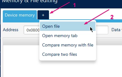 Figure 21 – File download on STM32 Cube Prog
Search for the web content binary file and open it. Connect the Nucleo board to the computer and press the green connect button on the top right corner. Afterwards, connecting the target information should be displayed on the bottom right corner and a "connected" text on the top right corner.
After making sure that the board is correctly connected, right-click the blue download button (2) and change the address to the one configured as the LevelX nor driver, 0x08100000 (3). After this, press enter, and the binary file will be downloaded to this address.
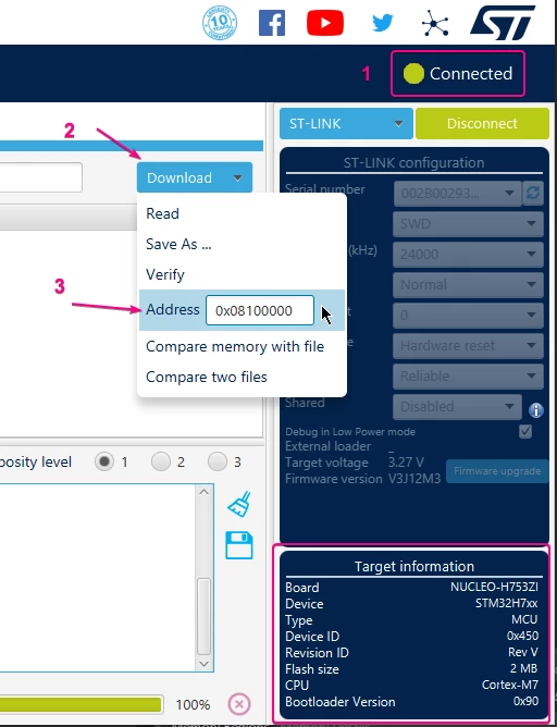 Figure 22 – File location address
Once the download is successful disconnect the board and move back to STM32CubeIDE.
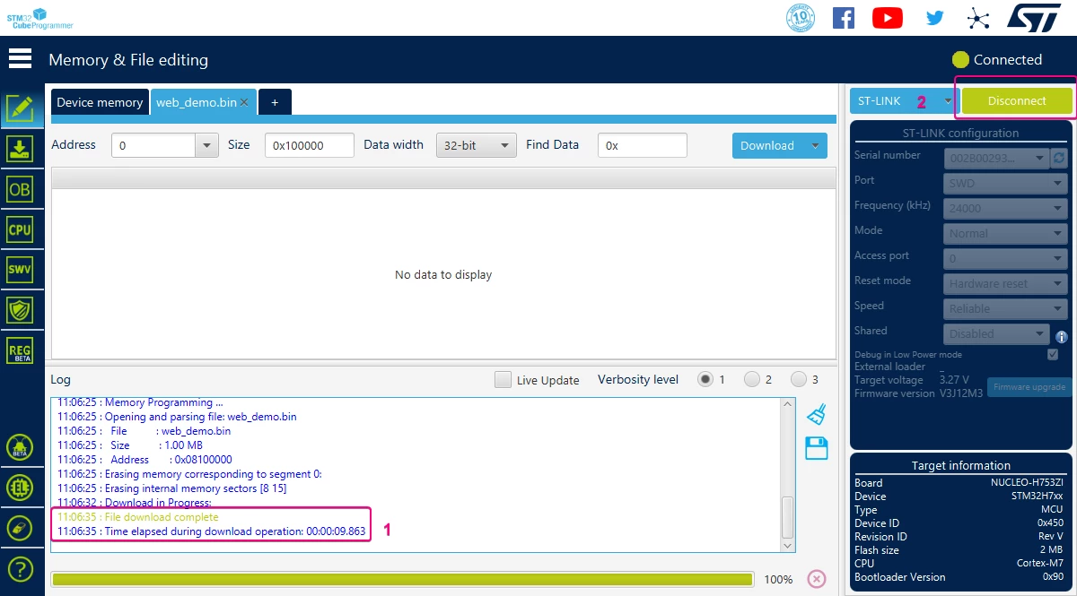 Figure 23 – File download confirmation
To download the code, there are two options: run mode and debug mode. Debug is preferred for the first launch since it makes error checking easier, thus it is going to be the method demonstrated here.
In STM32CubeIDE, left click the debug button or press F11.
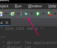 Figure 24 – Debug mode icon
A pop-up appears to configure the debug session, as the default settings are recommended, simply press ok on the bottom right corner.
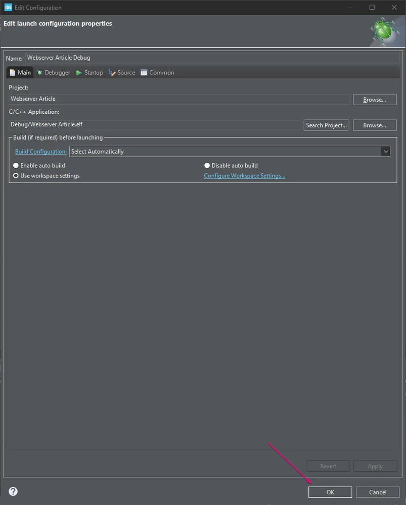 Figure 25 – Debug configuration tab
The project is rebuilt, and the perspective should be switched to the debug perspective. Now, the code is ready to run.
2.2 Code run and web page opening
A terminal interface is required for IP address checking and code flow, as well as specific debug. You can either use our favorite terminal software or set up the built-in terminal in STM32CubeIDE.
To configure the terminal, left click the console options on the bottom right corner and select command shell console.
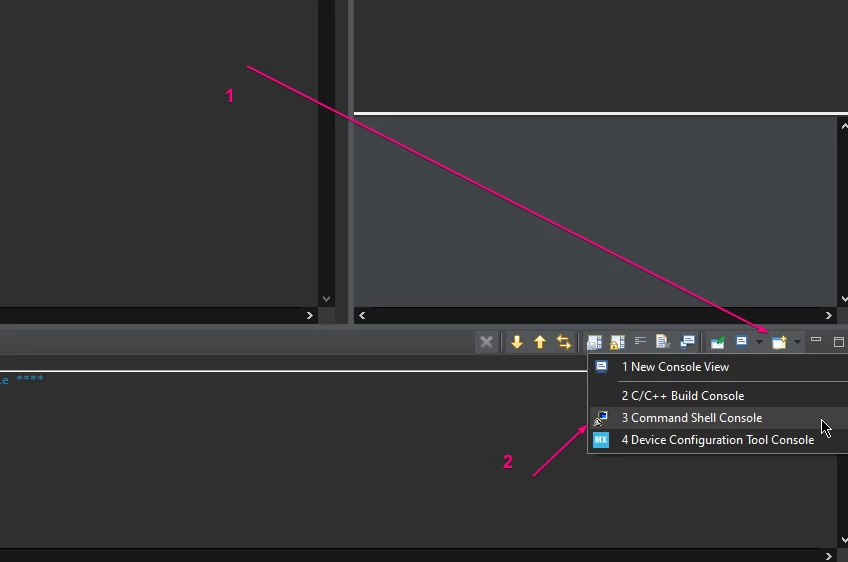 Figure 26 – Console opening
A setup pop-up appears, the connection type must be set to serial port, encoding to UTF-8, and press the new button to set up the serial port settings. Choose your USART3 configuration and press finish then ok.
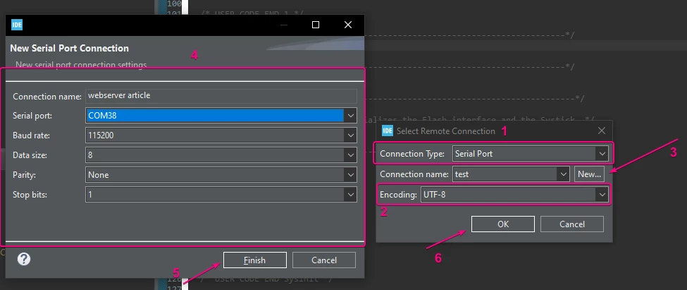 Figure 27 – Com port configuration
Make sure to connect the board using an RJ45 cable to a router or switch, then allow the code to run by pressing the resume button or the F8 shortcut.
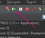 Figure 28 – Resume icon
On the terminal the following messages should be displayed if all steps were done correctly, the IP address varying based on your network’s addressing and architecture.
 Figure 29 – Application console output
Make sure that the computer is connected to the same network as the board is, be it via wireless connection or wired. Type the IP address into a browser, followed by either one of the three html pages present in the provided binary file: /about.html; /index.html; or /dashboard.html. The latter providing performance data collected from ThreadX and NetXDuo, and a toggle switch to toggle the board’s green LED blink.
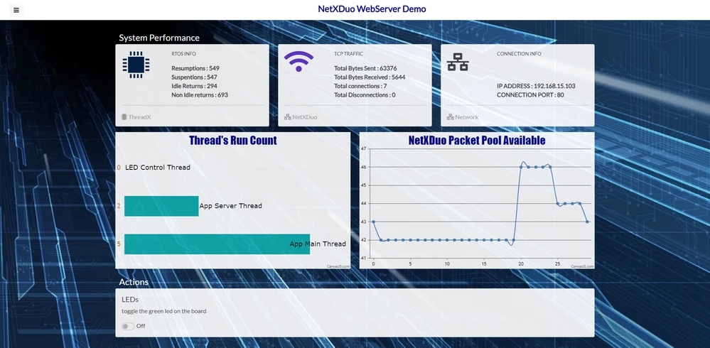 Figure 30 – Dashboard.html webpage
With the information displayed here, it should be possible to recreate and edit this application to develop your own web server, using the NetXDuo middleware and its support for the HTTP protocol. Creating new web pages with advanced features and applications is dependent on the developer. Integrating them into the memory is facilitated by the presented tool. We hope you enjoyed this material!
Related links
Here are some related links that can help you in your developments using our peripheral:
ST Wiki – Introduction to NETXDUO
MOOC – STM32 Azure RTOS workshop