


How to display an image stored in external flash on the STM32H7S78-DK using the LTDC controller
Introduction
The rapid evolution of embedded applications has profoundly transformed the design of modern electronic systems. This evolution is particularly evident in applications featuring graphical displays, where users expect interfaces that are more intuitive, more responsive, and visually more appealing.
The development of human machine interfaces has therefore encouraged the integration of advanced graphical elements and features into many embedded products. However, these graphical elements require a significant amount of memory, often exceeding the internal storage capacity of the microcontroller.
To address this need, STM32 microcontrollers integrate high-speed external memory interfaces, making it possible to add additional memory and extend system capabilities. This approach provides an effective solution for storing large graphical resources while maintaining strong access and display performance.
In this context, this article illustrates the use of external flash memory in a graphical application using the STM32H7S78-DK board.
-
Project overview
This example shows how to configure the LTDC interface to display an image. This image is stored in external NOR flash memory and accessed via XSPI2. It is displayed on the LCD screen mounted on the STM32H7S78-DK board.
-
Prerequisites
Hardware
- STM32H7S78-DK board
Software
- STM32CubeMX version 6.17.0
- STM32CubeIDE version: 2.1.1
-
Steps
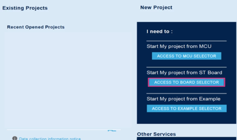
Step 1: Open STM32CubeMX and click the [ACCESS TO BOARD SELECTOR] button.
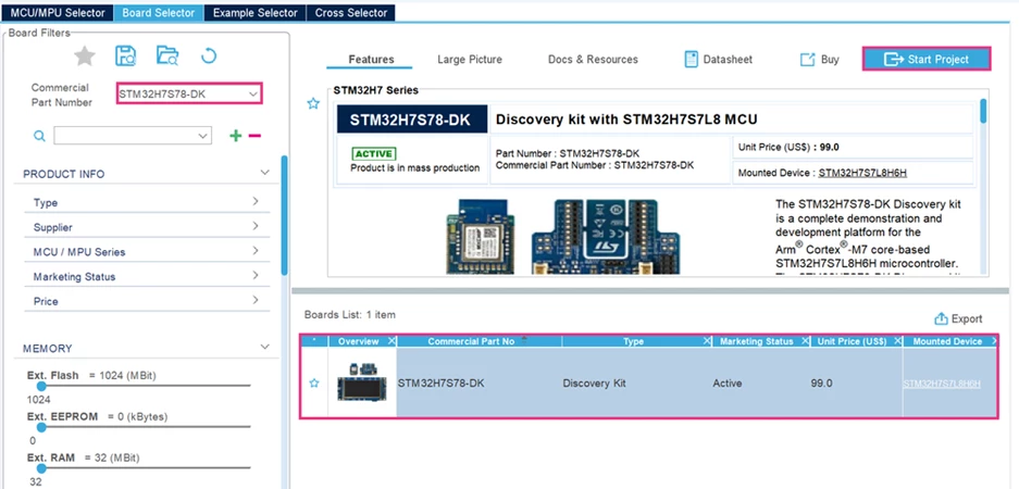
Step 2: Enter the relevant Part Number in the [Commercial Part Number] field. In this example, we use the STM32H7S78-DK board. Select it and click on [Start Project].
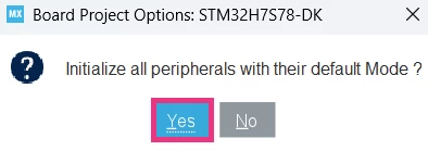
A pop-up appears, as shown in the screenshot below: Click [Yes].
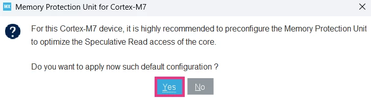
Another pop-up appears, click [Yes].
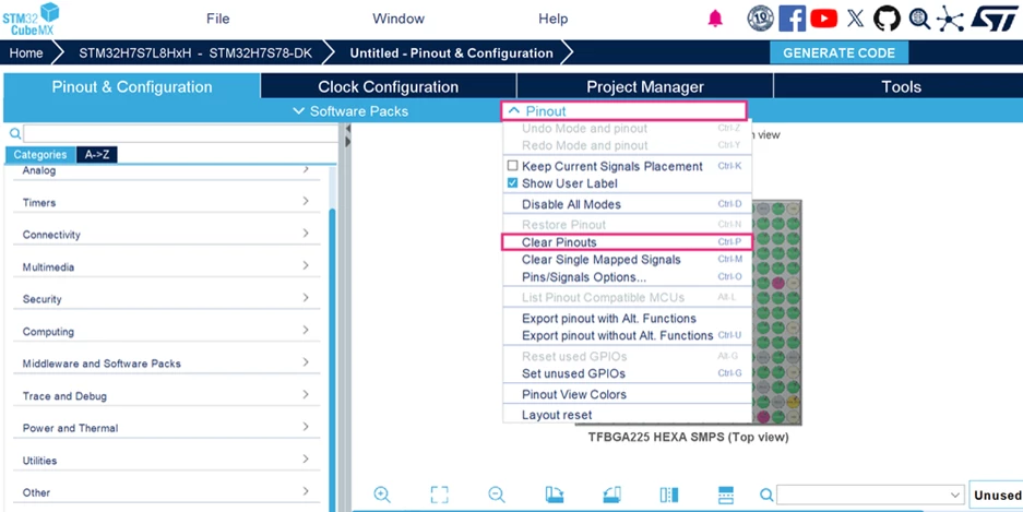
Step 3: Click [Pinout] and then [Clear Pinouts].
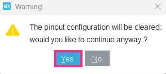
A pop-up appears, as shown in the screenshot below: Click [Yes].
Step 4: XSPI mode and configuration
To access and communicate with the external flash memory, configure the XSPI2 interface as shown in the screenshot below.
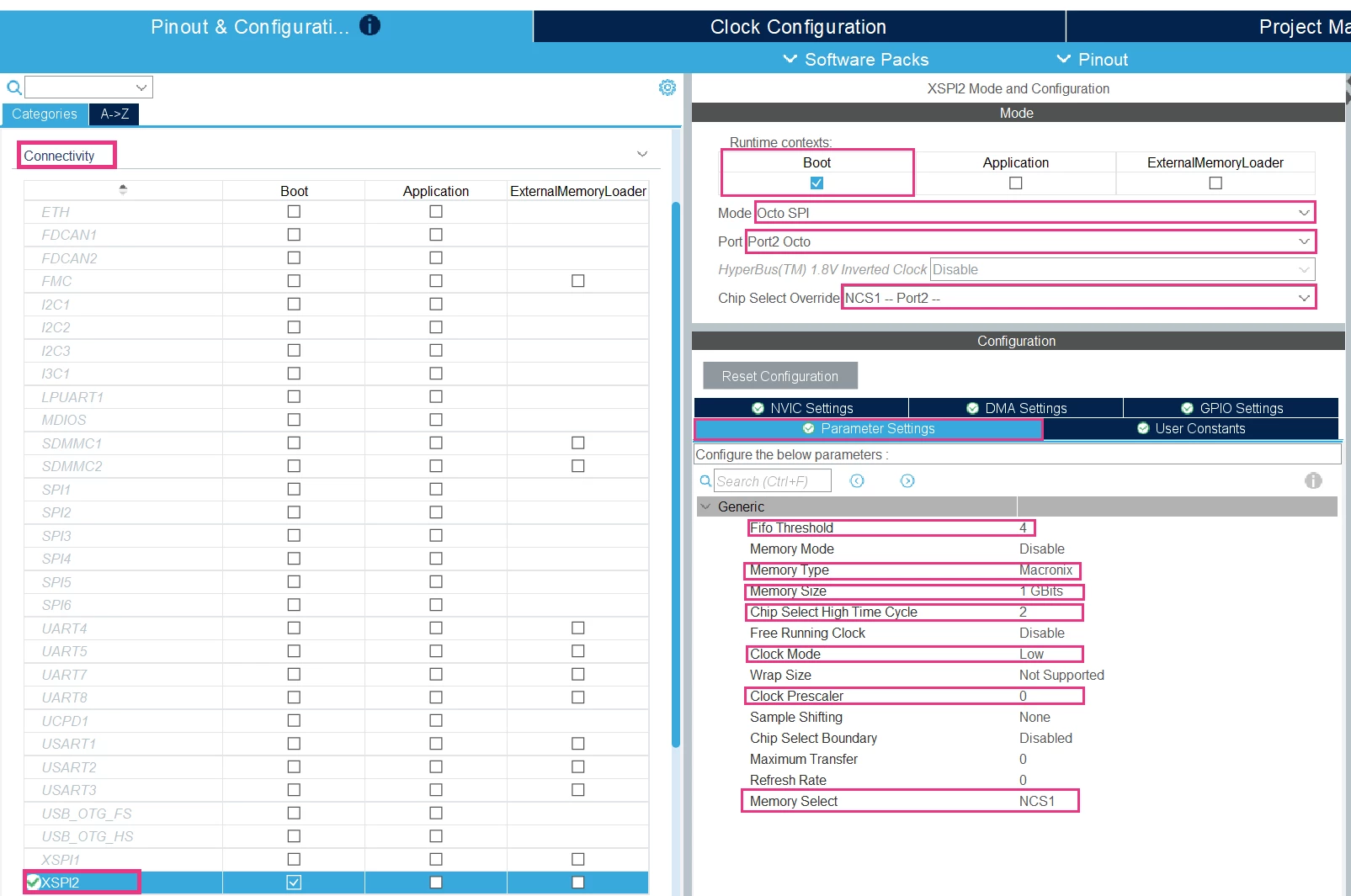
For the GPIO Settings, verify that the XSPI pins are configured “Very High”.
Note: For more details about the type of external flash memory and its specifications, refer to "How to configure the external flash memory MX66UW1G45G on the STM32H7S78-DK via XSPI interface" article.
Step 5: EXTMEM_MANAGER Mode and Configuration
- Activate the External Memory Manager
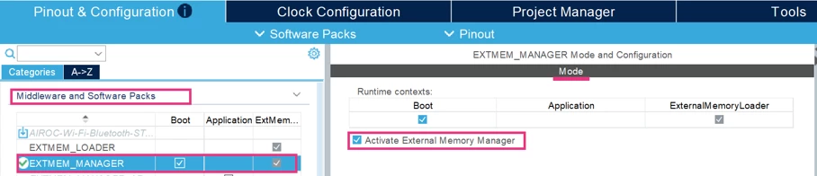
Enabling the External Memory Manager allows STM32CubeMX to generate the configuration and support code that manages the external flash memory automatically.
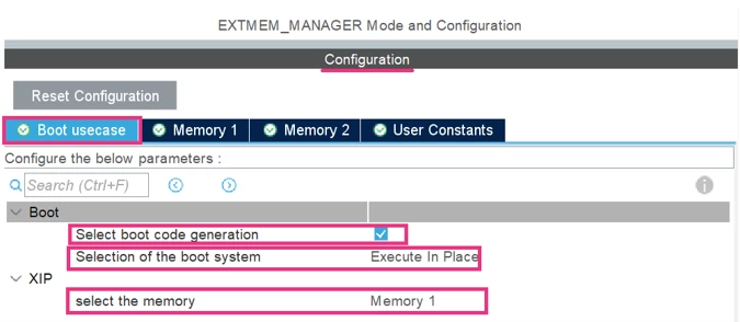
- For the Boot use case, configure it as shown in the screenshot below.
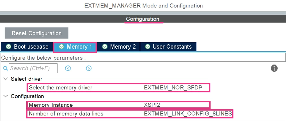
- For Memory 1, configure it as shown in the screenshot below.
Step 6: LTDC Mode and Configuration
The LTDC on STM32 MCU is an on-chip LCD display controller that provides up to 24-bit parallel digital RGB signals to interface with display panels.
Before configuring the LTDC, consult UM3289 -Rev 4, specifically section 8.1 TFT color LCD 800 × 480 pixels. This section helps users to identify the characteristics of the LCD panel integrated into the STM32H7S78-DK board and the related documentation to review.
To display an image on an LCD-TFT panel driven by the LTDC, all these parameters must be correctly configured: the Data Format, Timing Parameters, Display Layers, and GPIOs.
For the Data Format:
Configure it, as shown in the screenshot below.
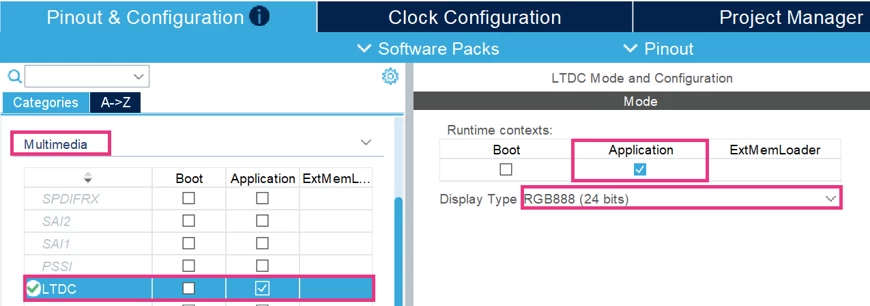
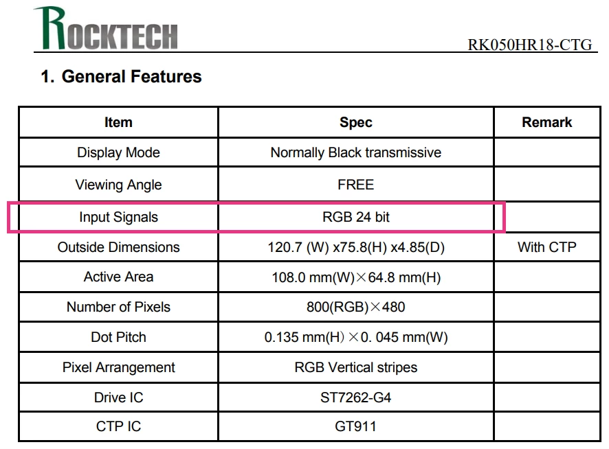
- Display Type = RGB888 (24 bits) → according to the RK050HR18-CTG datasheet, this type of LCD supports 24 bits, as shown in the screenshot below.
For the Timing Parameters:
Configure it, as shown in the screenshot below.
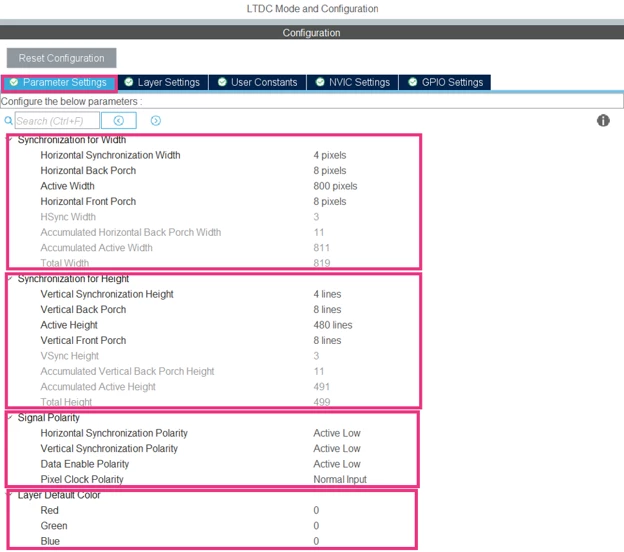
- Synchronization for Width:
This part concerns the horizontal timing of the line:
- Horizontal Synchronization Width (HSYNC-Pulse Width) = 4 pixels → indicates when a new line starts on the LCD panel.
- Horizontal Back Porch (HBP) = 8 pixels → indicates the blanking period before the active area. This period allows the display timing to stabilize before the display shows visible pixels.
- Active Width = 800 pixels → indicates the number of pixels displayed in one line.
- Horizontal Front Porch (HFP) = 8 pixels → it indicates the end of the line.
- Synchronization for Height:
This part concerns the vertical timing of an image:
- Vertical Synchronization Height (VSYNC-Pulse Width) = 4 lines → indicates when a new frame starts on the LCD panel.
- Vertical Back Porch (VBP) = 8 lines → indicates the blanking period before the active area. This period allows the display timing to stabilize before the display shows visible lines.
- Active Height = 480 lines → indicates the number of lines in one frame.
- Vertical Front Porch (VFP) = 8 lines → it indicates the end of the frame.
- Synchronization for Width: defines the active level of the signals.
- Layer Default Color: defines the default background color if no pixel is displayed (default black).
To understand the position of each parameter, refer to this picture:

To configure the Display Timings, extract the timing parameters from the device datasheet. Refer to the RK050HR18-CTG datasheet as shown in the screenshot below.
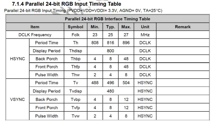
Note: We recommend using the standard display timings.
For the Display Layers:
Configure it, as shown in the screenshot below.
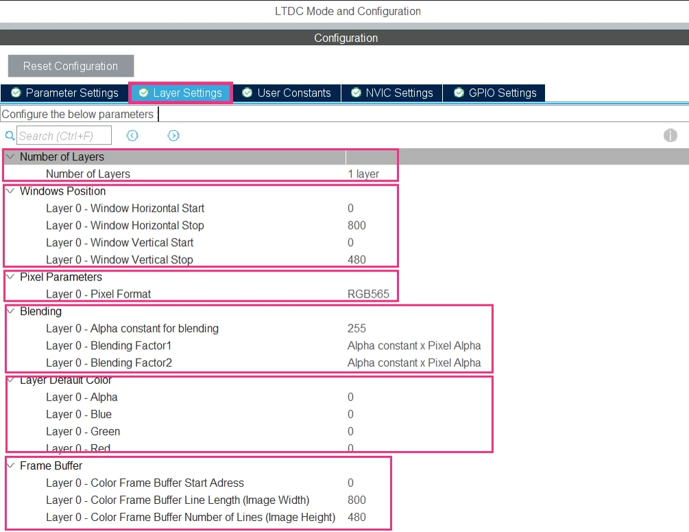
For more details about these parameters, refer to AN4861 - Rev 7 specifically section 7.2.4 LTDC peripheral configuration
For GPIO Settings:
Select all the LTDC pins, then set the Maximum Output Speed to “Medium”.
The configured GPIOs must match the LTDC connection as shown in the schematic board MB1736 figure below. If the configuration is not correct, the user must manually configure all the GPIOs one by one clicking directly on each pin.
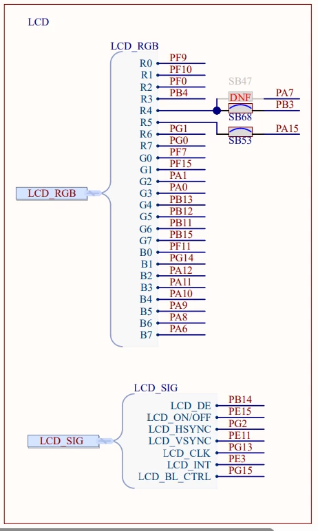
Note: In this case, the pin PA2 was changed to PA6 according to the schematic.
Once all LTDC interface pins are correctly configured respecting the LCD-TFT panel connection, configure the other specific pins connected to the display (LCD_ON/OFF: PE15 and LCD_BL_CTRL: PG15) as an Output Push-Pull with High Level to enable the display, otherwise the display stays in standby mode, as shown in the screenshot below.
Note: The LCD_INT pin is not configured because it is an interrupt pin, used only when an external event must be handled. In this example, we only use image display with the LTDC, so LCD_INT is not needed.
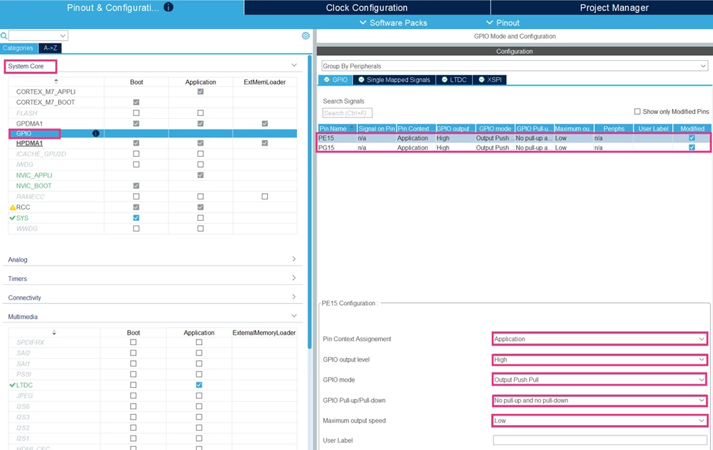
For more details about the GPIO configuration, refer to the AN4861 -Rev7, specifically section 5.7.1 Display panel connection.
Step 7: SBS Mode and Configuration
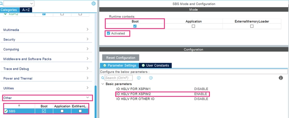
Enabling HSLV is recommended in cases when the XSPIM domain is powered by 1.8V and operates the serial memory interface at its maximum speed of 200 MHz.
Note: For more details about HSLV, refer to this FAQ: “Recommendations for high-speed low-voltage mode (HSLV) on the STM32H7RS”.
Step 8: Clock Configuration
- MCU Clock Frequency = 600 MHz
- f_Kernel = 200 MHz
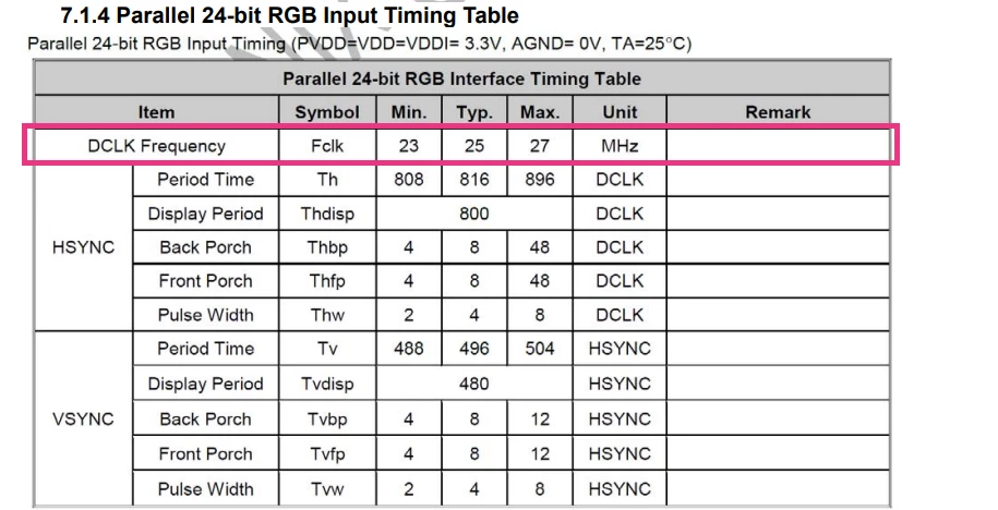
- LTDC Frequency = 25 MHz
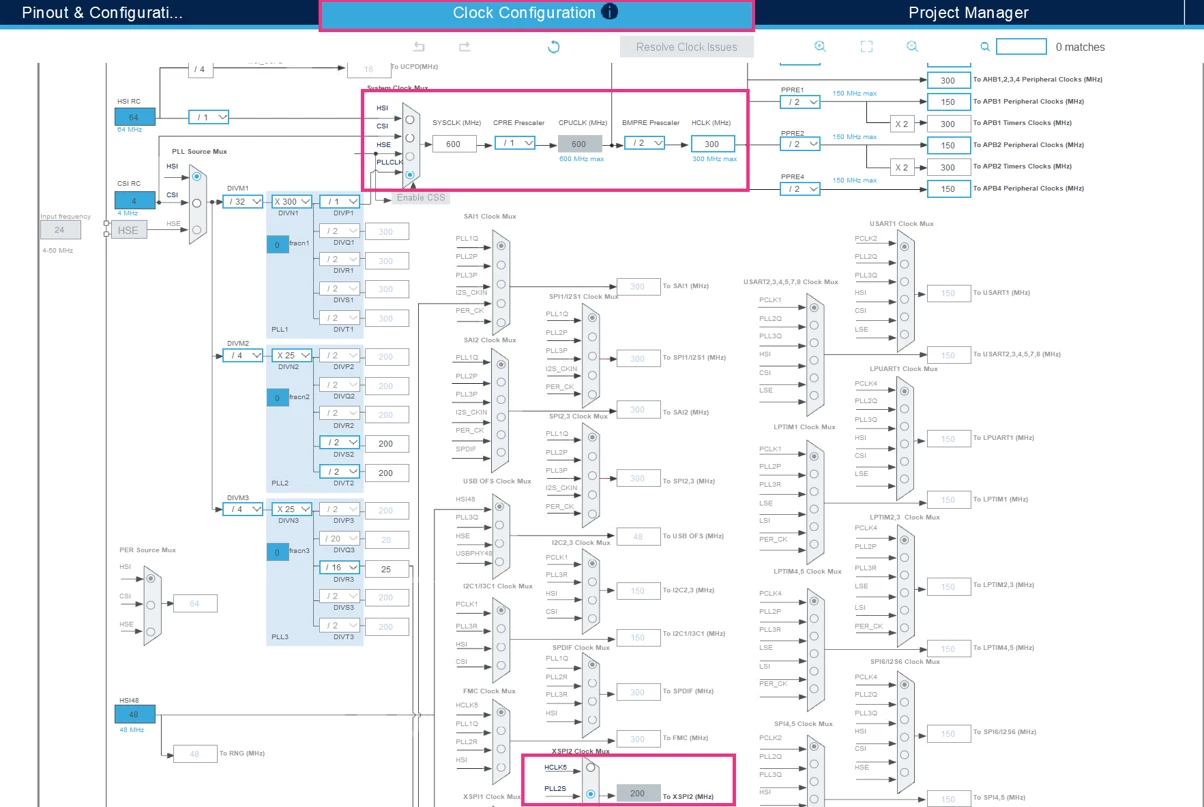
For the LTDC Frequency, refer to the RK050HR18-CTG datasheet, as shown in the screenshot below.
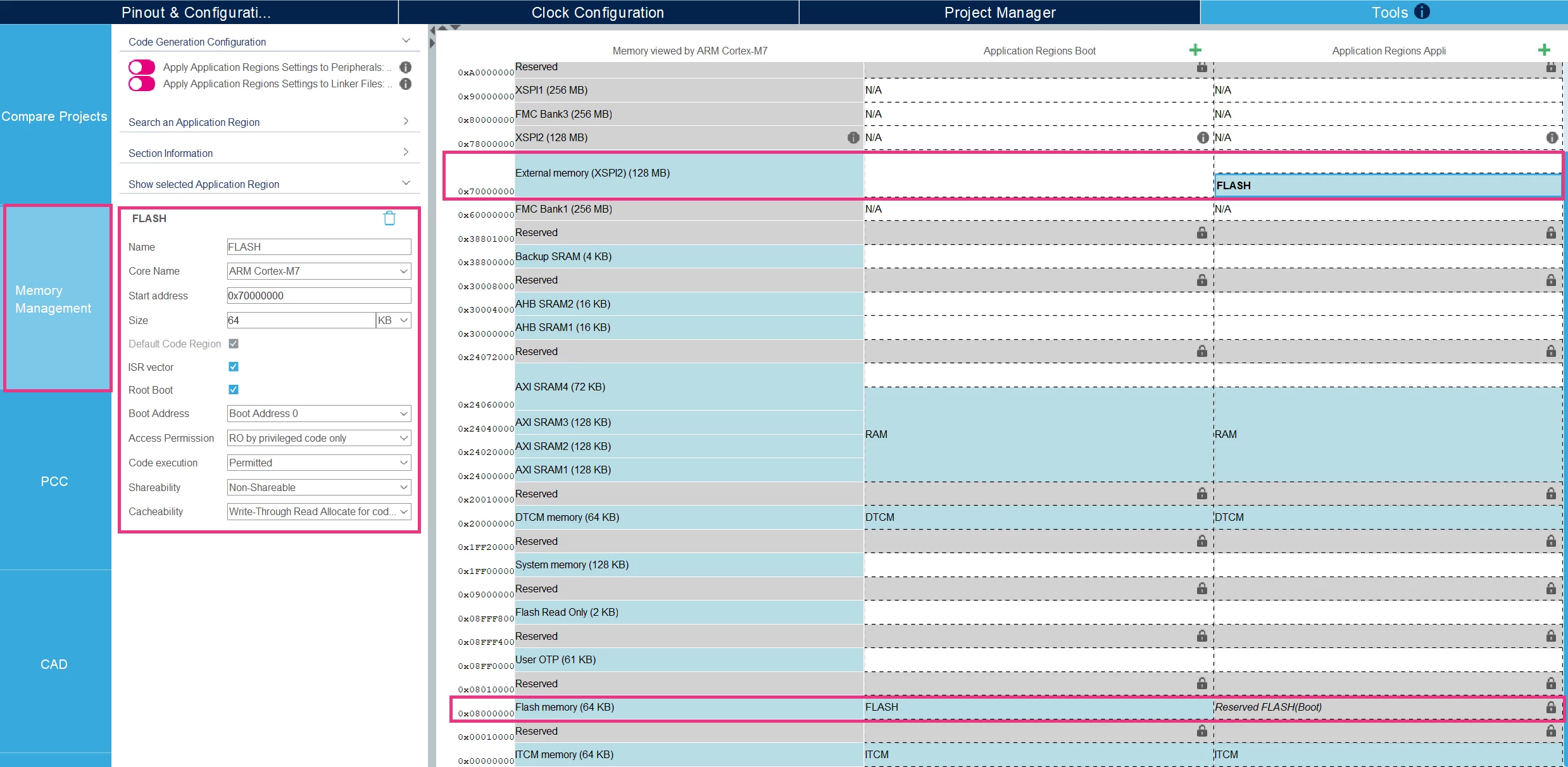
Note: Ensure that the Memory Management is configured as shown in the screenshot below.
Step 8: Generate Code
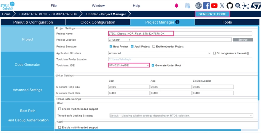
Enter the Project Name, choose the Toolchain/IDE and click [GENERATE CODE], as shown in the screenshot below.
Step 9: Image Conversion
To display the image from external memory, the picture must be converted into a pixel format compatible with the LTDC framebuffer. This conversion allows the LTDC to read the image directly and show it on the LCD-TFT panel.
Note: The size of the image used must be aligned with the LTDC Layer1 configuration (800 x 480). If the used image size is not aligned with the LTDC Layer1 configuration, it must be resized or choose another image with the correct size.
To convert the image, use the LCD-Image-Converter-20190317 tool by following these steps:
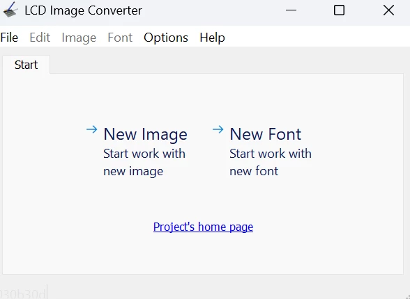
- Open the LCD-Image-Converter
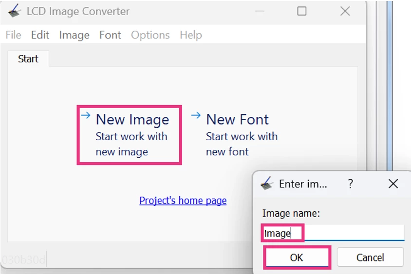
- Click [New Image], enter the image name, then click on the [OK] button
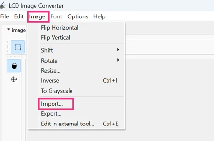
- Click [Image], then click [Import]
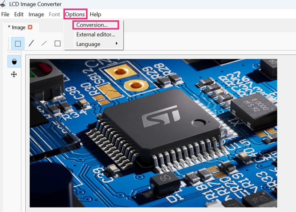
- Click [Options], then click [Conversion]
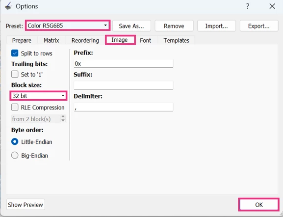
- Select [Color R5G6B5] in the Preset field. Set the Block size field to [32 bit]. Then click on the [OK] button
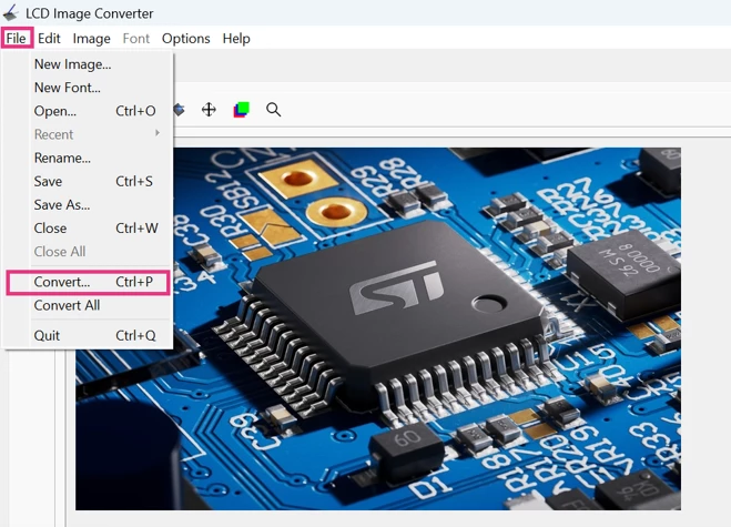
- To generate the header file, click [File], then click [Convert]
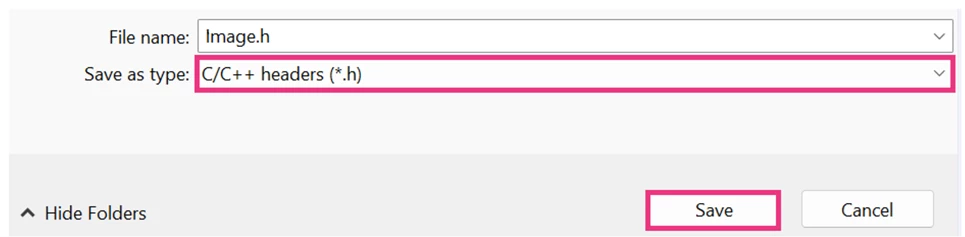
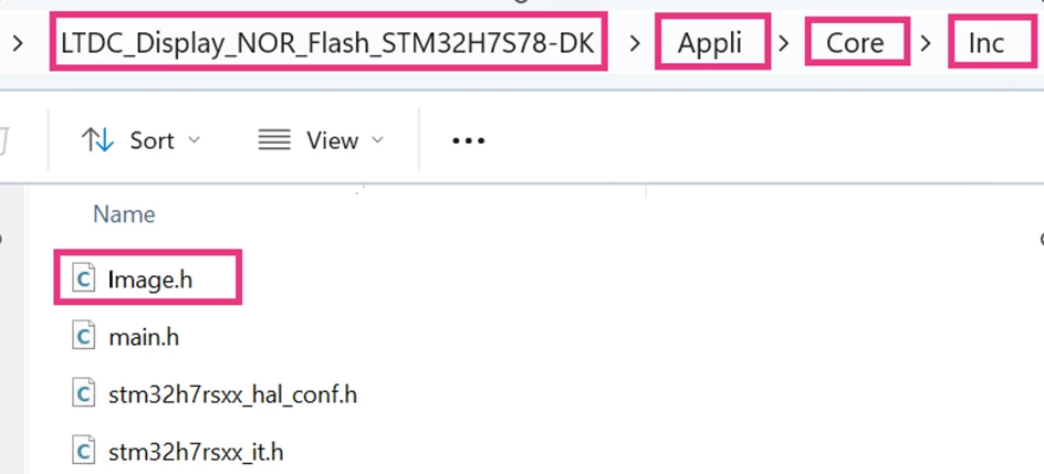
- Set the file type to [C/C++ headers (*.h)]. Then, save the *.h file in the included directory, where the main.h file of the Application project is located.
Step 9: Edit main.c in the Application project
After generating the project with STM32CubeMX, the generated header file (Image.h) and the Framebuffer Start Address used by the LTDC must be included in main.c.
- Insert Image.h in the Private includes section:
/* USER CODE BEGIN Includes */
#include "Image.h"
/* USER CODE END Includes */
/* USER CODE BEGIN Includes */
#include "Image.h"
/* USER CODE END Includes */
- Set the framebuffer start address used by the LTDC:
  pLayerCfg.WindowX0 = 0;
  pLayerCfg.WindowX1 = 800;
  pLayerCfg.WindowY0 = 0;
  pLayerCfg.WindowY1 = 480;
  pLayerCfg.PixelFormat = LTDC_PIXEL_FORMAT_RGB565;
  pLayerCfg.Alpha = 255;
  pLayerCfg.Alpha0 = 0;
  pLayerCfg.BlendingFactor1 = LTDC_BLENDING_FACTOR1_PAxCA;
  pLayerCfg.BlendingFactor2 = LTDC_BLENDING_FACTOR2_PAxCA;
  pLayerCfg.FBStartAdress = (uint32_t)image_data_Image;
  pLayerCfg.ImageWidth = 800;
  pLayerCfg.ImageHeight = 480;
  pLayerCfg.Backcolor.Blue = 0;
  pLayerCfg.Backcolor.Green = 0;
  pLayerCfg.Backcolor.Red = 0;
Note:
- The Frame Buffer Start Address value is found in the Image.h file, as shown in the screenshot below.
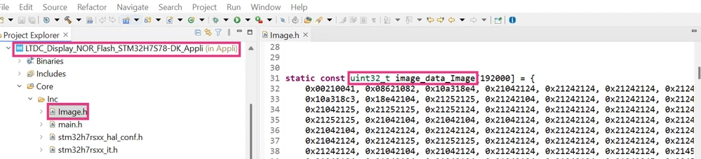
- In the same file (Image.h), the user must comment out the structure definition after the table. They should keep only the table definition, as shown in the screenshot below.

Step 10: Build the Application Project
- Click the [build] button.

Step11: Debug and Verification
To debug the project without flashing the boot every time, follow the steps described in this article: “STM32CubeIDE: How to debug an STM32H7Rx/Sx project without flashing boot every time”.
- Click the [resume] button.

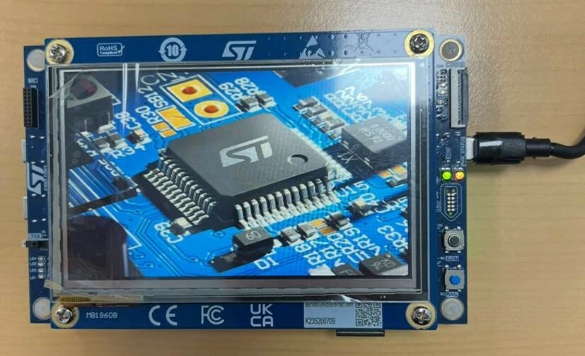
The screenshot below shows that the image displayed on the LCD panel confirms that the framebuffer content is correctly stored in external memory and properly rendered by the LTDC.
For additional verification:
- Click on [Window], then select [Memory Browser], as shown in the screenshot below.
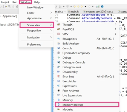
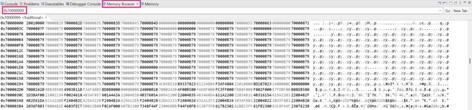
The Memory Browser is used to inspect the content of the external memory region and verify that the external memory is correctly accessible in memory-mapped mode.
The raw data stored in external memory can be accessed by entering the corresponding address of the memory-mapped external NOR flash. This flash is accessed through XSPI2 and is mapped at 0x70000000 and visualized at this address location. This occurs once the application reaches memory-mapped mode. The External Memory Manager automatically manages it. This confirms that the external memory is correctly configured and that the LTDC can read the image data from the expected location.
Conclusion
After following this guide, configuration of the LTDC with external flash memory MX66UW1G45G through XSPI2 enables display of an image on an LCD using the STM32H7S78-DK board.
To access the final project files and the image used, download the extractable file attached at the bottom of the article.
Related links
- Application note AN4861: Introduction to LCD-TFT display controller (LTDC) for STM32 MCUs
- User manual UM3289: Discovery kit with STM32H7S7L8 MC
- Reference Manual RM0477: STM32H7Rx/7Sx Arm®-based 32-bit MCUs
- Datasheet: STM32H7S3x8 STM32H7S7x8
- RK050HR18 Datasheet: ROCKTECH LCD Module Specification
- Knowledge Base Article: STM32CubeIDE: How to debug an STM32H7Rx/Sx project without flashing boot every time
- Knowledge Base Article: How to configure the external flash memory MX66UW1G45G on the STM32H7S78-DK via XSPI interface