James1
Associate II
October 23, 2018
Solved

Fluctuations in ADC value of STM32H743 MCU

  • October 23, 2018
  • 26 replies
  • 15793 views

Hi,

I have been working with STM ADC’s from quite a long time. I had used STM32F373 and F4 series MCU ADC’s earlier for my applications. As, now my application requires huge amount of RAM, memory and computation speed I have shifted to STM32H743 MCU . Earlier when I used F3 series ADC the noisy LSB was around 4 LSB which is a quite good resolution for 16 bit ADC . But as I have shifted to STM32H743 the noise level fluctuation is around 300LSB for 16 bit ADC resolution for single ended channel. When I hook up ground to ADC pin it shows a value fluctuation of about 100LSB . I use Analog accelerometer for my application and I need to see a resolution of 1 mg and with such amount of noise I won’t be able to achieve such high resolution.

The code is generated using CubeMx.The ADC is clocked using external clock and the MCU is powered from a 3.3 V regulator supply and Analog and digital grounds are properly separated.

I checked into their errata sheet and I couldn’t find any possible solution.

Any solutions will be highly appreciated .

Thank you

This topic has been closed for replies.
Best answer by omuzychko

PROBLEM SOLVED

Appears to be an issue of the Nucleo-144 demo-board itself (NUCLEO-H743ZI specifically), NOT AN STM32H7 FAULT!

HOW TO FIX?

  • Desolder/remove L2 ferrite bead to disable Ethernet PHY chip (see Nucleo-144 schematic, it is located close to that IC nearby Ethernet port).
  • Or use NUCLEO board without Ethernet hardware (OOOPS ... not available for H7)
  • Alternatively you may remove SB2, but that will disable USB-port circuitry as well

WHY?

  • This chip designated to PAM-modulate and amplify the Ethernet signal before feeding it into long wires of CAT5/6 cable.
  • Apparently it does not have any low-power/standby mode when not in use.
  • So even if you not use it - its clock (25MHz) injected into board circuitry (my guess - over the ground). Observed at ADC with 5mV peak-to-peak swing, basically reducing ADC resolution to 10-bits!

Can you have Ethernet and clean ADC capture at the same time?

  • Somewhat possible with oversampling or moving-average filter.
  • 16-samples needed to get 12 effective bits of resolution, but limits your acquisition bandwidth to around 100kHz

And here is my story of how did I figured it out:

First of all - sorry for a delay since my last reply. To approach this problem I had to wait for a good weekend (free of other tasks and events) since I decided to go "full ballistic" to eliminate any guess work:

  1. The Nucleo-144 board has been put into 3D-printed enclosure which was painted with MG Chemicals Super Shield conductive paint to block any external EMI sources.
  2. I've wired ADC inputs to 1.5V AAA battery. The wires were as short as I could get and battery did fit into shielded enclosure of the Nucleo board.
  3. I've used external power supply 8..12V.
  4. Also the ADC analog block (AVDD) was powered form the same LDO as the MCU itself. So MCU digital blocks can interfere with the ADC. It is always recommeded to use separate supply and even dedicated Vref for ADC. So I've soldered a separate circuit with 3.3V LDO isolated from the main external supply by capacitance multiplier (see EEVBolg youtube video on what is that: https://youtu.be/wopmEyZKnYo ).
  5. So SB12 (see Nucleo schematic) was de-soldered to connect this new clean-output LDO to AVDD. SBL162 was de-soldered as well and AGND was wired directly to the LDO ground pin. In other words AVDD and AGND of the nucleo board were now wired directly to its dedicated LDO.
  6. Test DC-signal source , the negative tab of 1.5V AAA battery was wired to the LDO ground. Eliminating ground loops for signal source.
  7. Add more bypass-capacitors for analog supply pins (soldered few more MLCCs on top of C34)

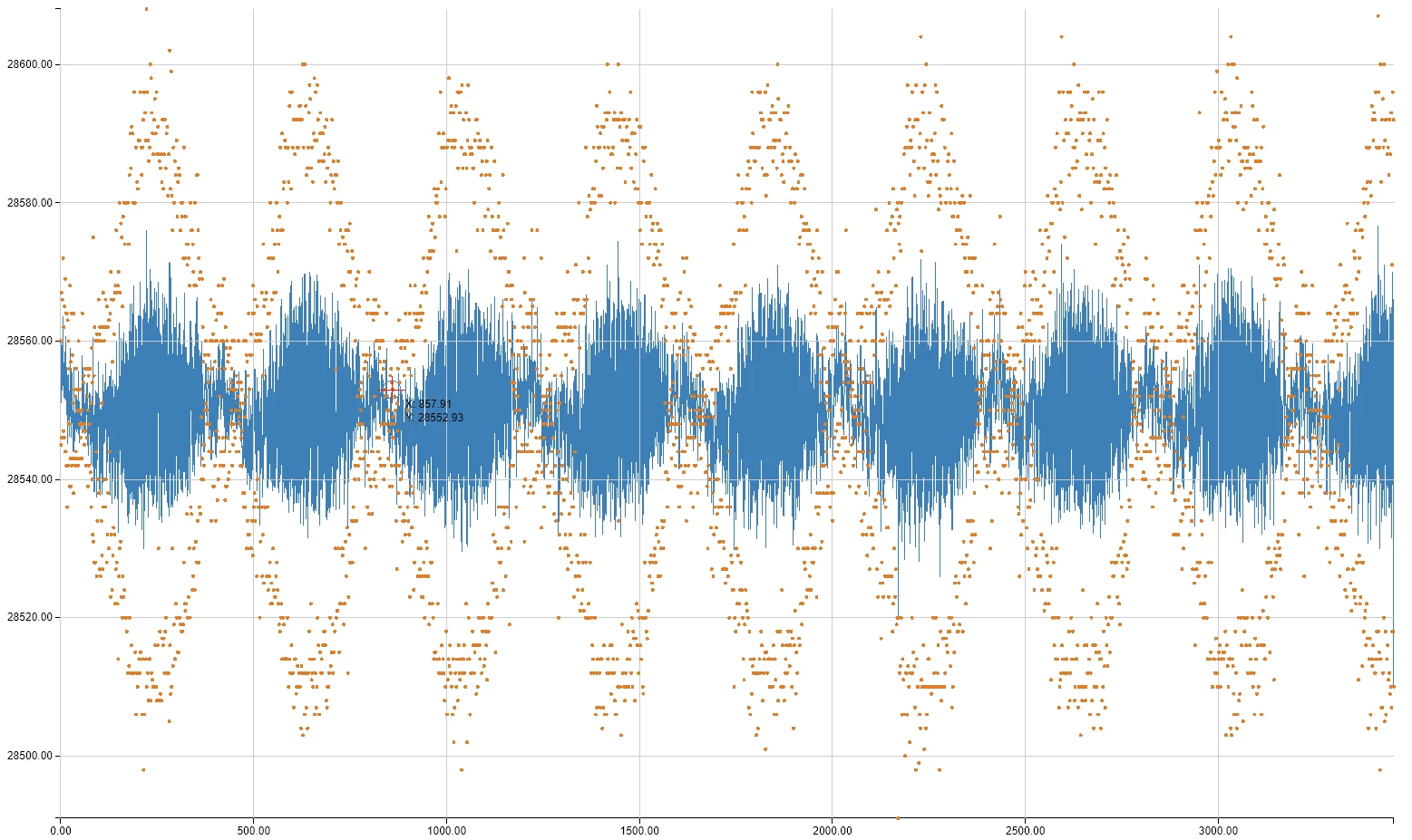
And then I've got the same high-speed (2 MSPS) raw data captures again:
0690X00000ApTaUQAV.png

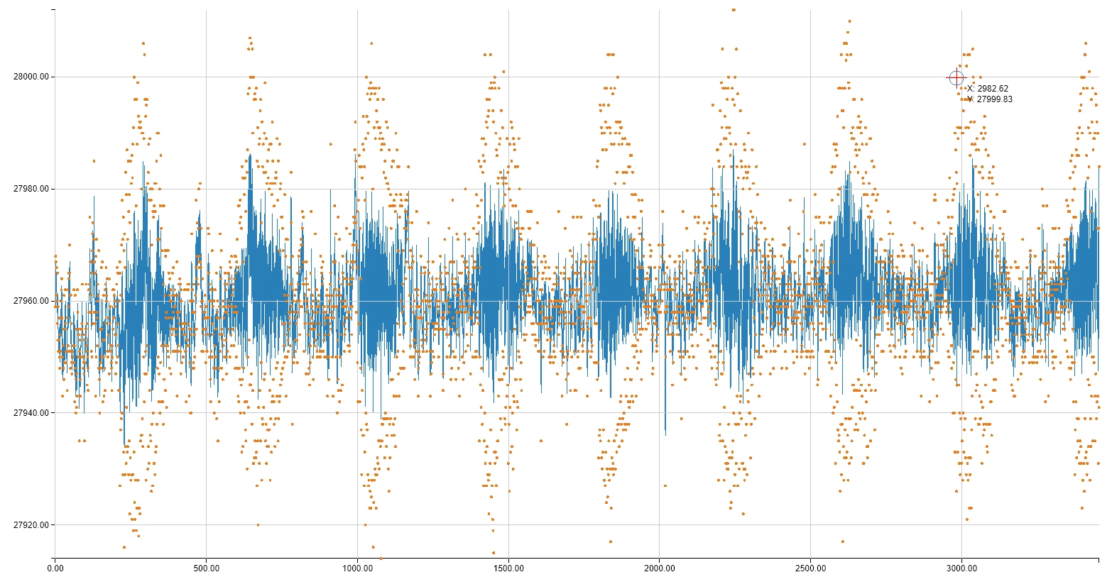
as you see it still shows this aliasing affect, but it looks now way cleaner and more "pronounced" than it was before:
0690X00000AA9YCQA1.png

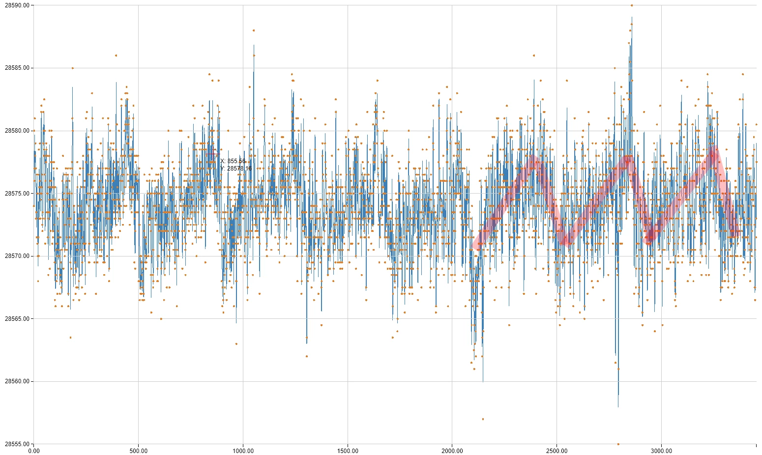
If using moving average filter using 2 samples, it improves slightly:
0690X00000ApTcVQAV.png

Trying to run ADC at its maximum sampling speed (5MSPS) did not help to figure out interference frequency, so it is higher than that.

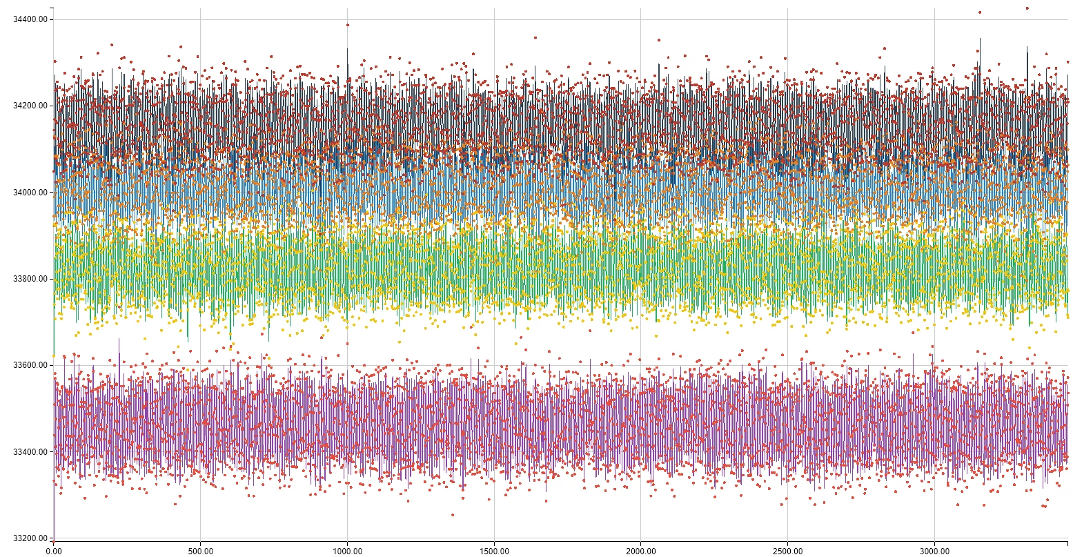
As I've already mentioned in my previous post - you can not identify that this is aliasing of higher-frequency interference IF you do slow sampling. As in this 13kSPS example it just looks like Gaussian noise, because clock drift (PLL jitter) introduces a lot of phase noise to notice any aliasing patterns of 13kHz vs 25MHz interference.
0690X00000ARCUsQAP.png

For these who don't now:

ADC aliasing happens when there is higher frequency at your ADC input than the Nyquist frequency (more than 1/2 of you sampling speed). You can not work with this kind of acquired data if you want to do any decent signal processing on it. In all good designs ADC inputs are guarded with good low-pass filters. Here is good example from the web (https://e2e.ti.com/blogs_/archives/b/precisionhub/archive/2015/09/04/aliasing-in-adcs-not-all-signals-are-what-they-appear-to-be)
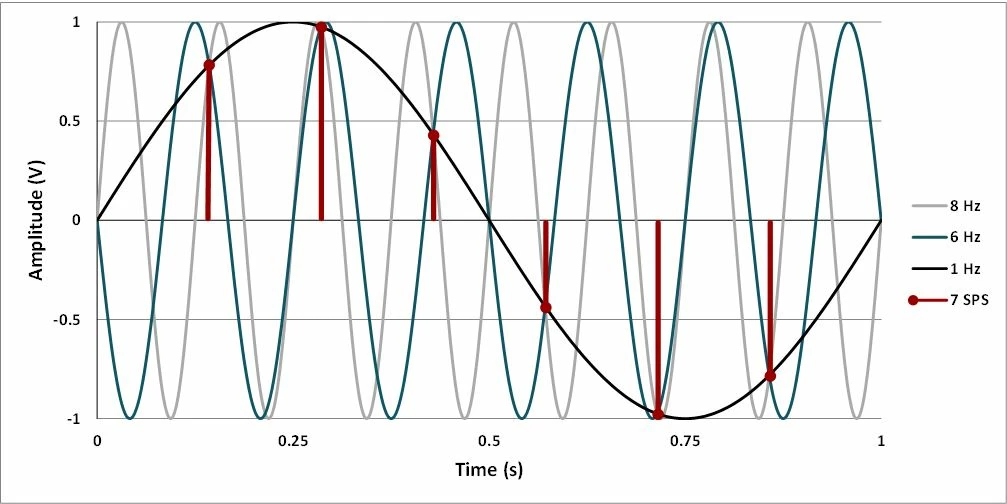
0690X00000ApTaeQAF.jpg

As you see 6 and 8 Hz signals can not be reproduced properly when sampling at 7Hz, you see that as 1Hz signal on ADC output.

In our case - the parasitic input was way beyond my Nyquist frequency of 1Mhz. If we zoom-in time scale of the first picture and plot it in MATLAB:
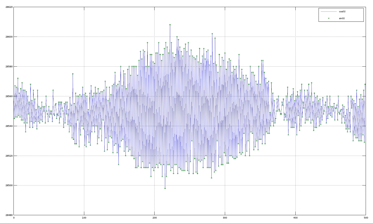
0690X00000ApTajQAF.png

The parasitic signal is apparently at 5mV peak to peak range (100 LSB out of 65536 for 3.3V full range).

Since all external sources were eliminated by shielding and ADC is powered by dedicated clean LDO there are few reasons left:

  • Internal issue in STM32H7 - highly unlikely. In datasheet we have SINAID specified at 82dB for single-ended input. If my calculations are correct - it should be equivalent of 5LSB RMS-noise. In other words - if measuring a perfect DC signal (from AAA-battery) 68% of samples should be with-in 10LSB range, and 99.7% for Gaussian noise should be with-in 30LSB peak-to-peak range.
  • Interfering signal source is some other component on the Nucleo-144 board, could be ST-Link as well getting something from USB-grouding.

To figure this out you need a spectrum analyser, LNA amplifier and H-field probe (https://youtu.be/crs_QLuUTyQ)

You can go cheaper way and get an SDR radio USB dongle with self-made H-field probe (https://www.stupid-projects.com/emc-probe-using-rtl-sdr)

I've found and ordered an MSi.SDR that has a perfect range for 10kHz to 2GHz for MCU board purposes.

Without having a patience to wait for SDR and semi-rigid coax delivery I've used an oscilloscope probe which came tip-to-BNC adapter. Using another female-to-feamale BNC-connector, piece of copper wire, aluminum foil and electric tape I've got an E/H-probe in like 20 min:
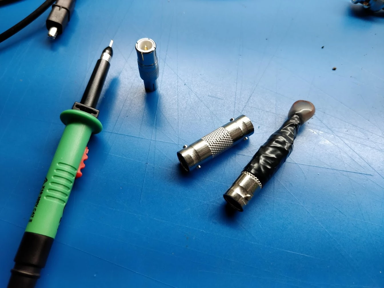
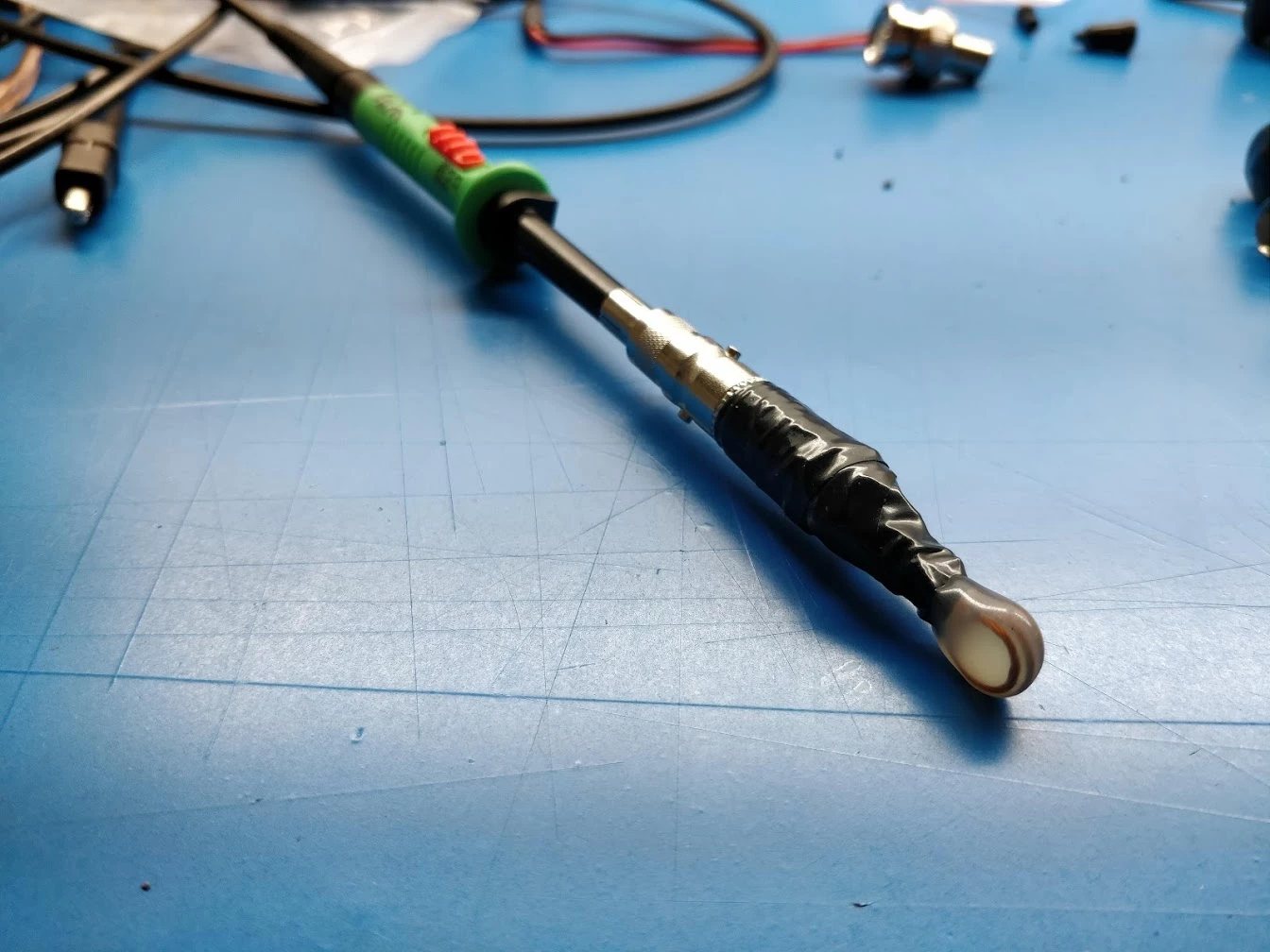
0690X00000ApTbcQAF.jpg0690X00000ApTbhQAF.jpg

With this contraption I was simply observing waveform on the scope and sniffed the interference source when I've stick it into Ethernet PHY IC package. I was lucky it was powerful enough to get me 5mV spikes on the scope without the need of any LNA.

Here is the raw sampling after I've thrown away an L2 ferrite bead. It should actually serve as a filter connecting a +3V3V_PER peripherals supply line to Ethernet PHY circuitry, but apparently interference is so strong that it propagates through the ground, or EMI into the wires connecting my DC-signal source to ADC input(s).

Here is the RAW capture of DC-signal source (AAA battery) after the hack:
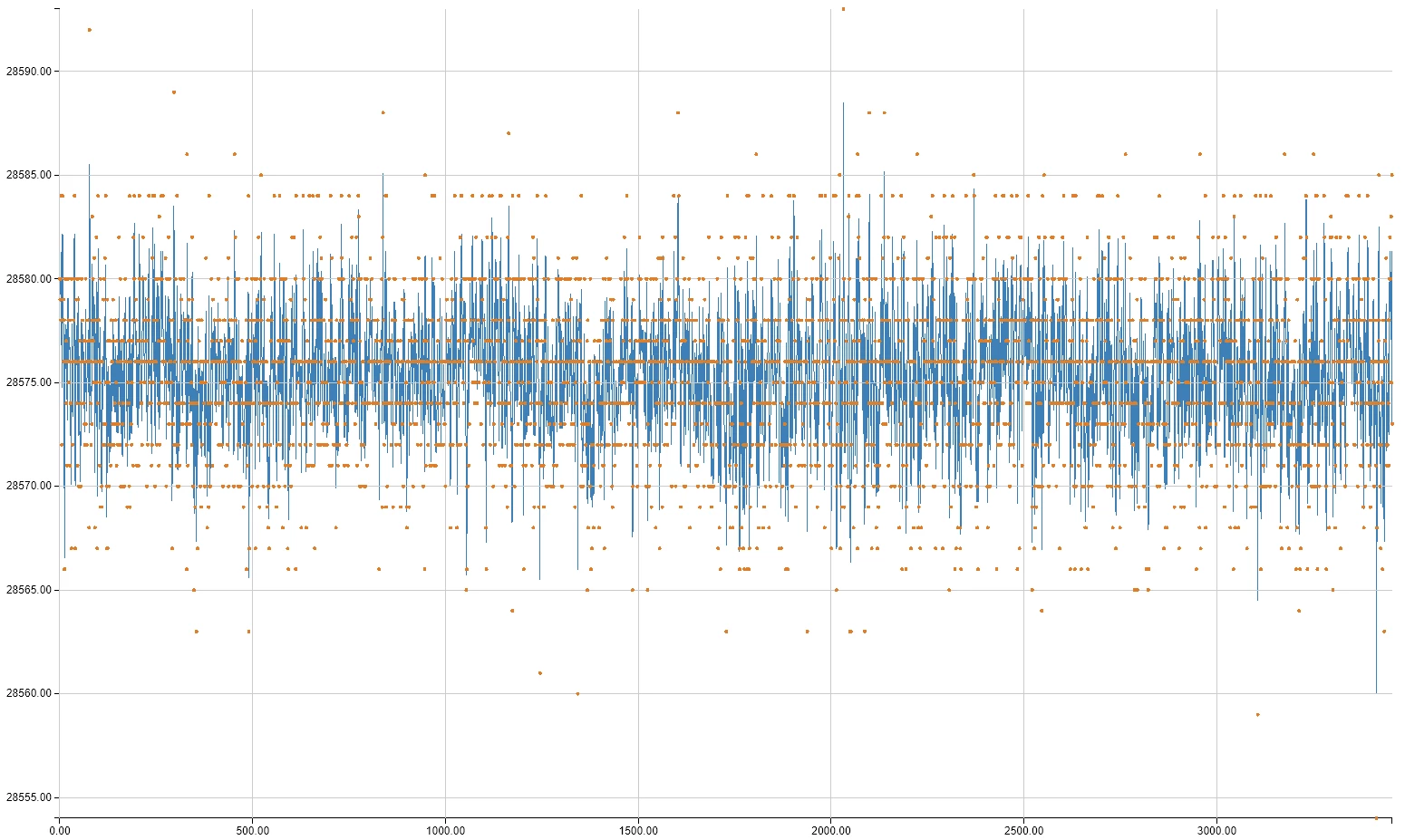
0690X00000ApTc1QAF.png

And here its overlay (red) with the RAW capture before disabling Ethernet PHY (blue):
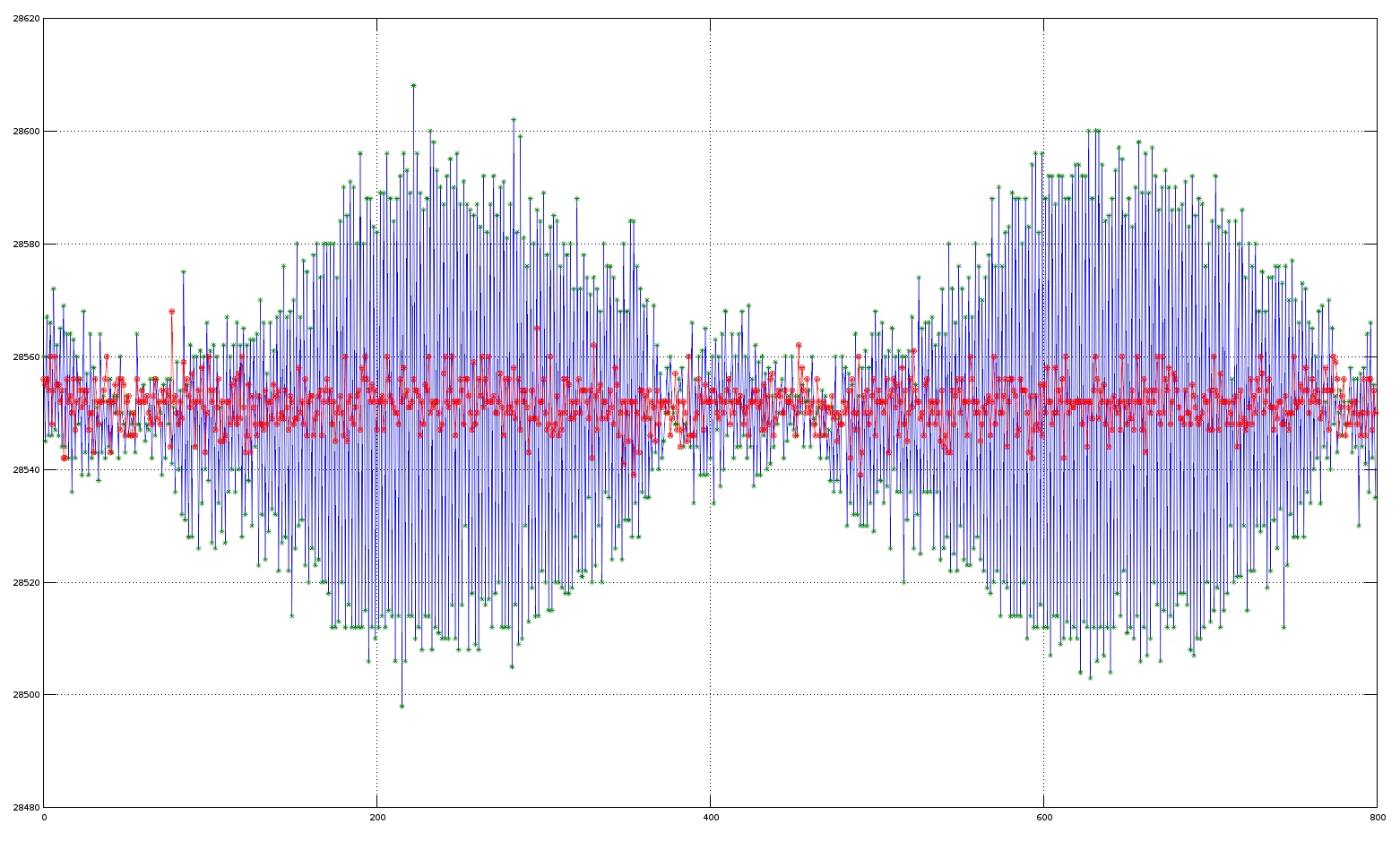
0690X00000ApTcGQAV.png

As you see - I've got it all well within spec, major half of samples are somewhat in 10LSB peak to peak range, while all of them within 30LSB.


26 replies

omuzychko
Visitor II
October 13, 2019

Got my MSi.SDR delivered, so made an H-field probe to see more what spectrum is radiated from Ethernet PHY chip:

0690X00000ApzGgQAJ.jpg

Using RSP Spectrum Analyser software, here is the spectrum when the probe is far away from the Ethernet PHY chip:

0690X00000ApzJzQAJ.png

And this is when the probe is close as shown on the picture above:

0690X00000ApzM0QAJ.pngSo that 25MHz frequency (of the XTAL nearby Ethernet PHY chip) is actually multiplied by 4, so we have 50MHz and 100MHz components in radiated EMI.

MDief.12
Explorer II
October 14, 2019

Thanks a lot for this great analysis.

I can confirm that removing the ferrite bead of the PHY drastically improves the analog performance.

I tested it with a NUCLEO-H743ZI2 eval board and also with custom board which uses a different PHY.

omuzychko
Visitor II
October 22, 2019

Hey Matthias,

I have unrelated question:

You've mentioned that you use newer NUCLEO H743ZI2 (I've am using a regular ZI).

Does your board has newer revision "V" of STM32H7 on it? The one that can run at 480MHz?

https://www.st.com/resource/en/errata_sheet/dm00368411.pdf

MDief.12
Explorer II
October 23, 2019

Yes, my NUCLEO H743ZI2 has a Revision V Chip on it.

omuzychko
Visitor II
October 22, 2019

Unrelated update:

So SDR appears to be a great cheap alternative replacement for Spectrum Analyzer to do near-field E/H-emissions testing. Or troubleshooting interference sources as it was discovered with Nucleo STM32H7 board in this thread.

After some more researching in SDR comunity I've figured that MSi.SDR while beeing the cheapest radio capable to pickup in kHz band - is not the ideal.

MSi.SDR is a cheap Chinese clone of RSP1 from SDRPlay. It has issues with spectrum output when there are no signal connected (no antennae or probe on its input) - see my first picture of the spectrum in previous post. It has spurs of 24Mhz and some of its multiples (48MHz, 120Mhz, 144Mhz).

24MHz - is the XTAL you may find on MSi.SDR board if you take it apart.

Today for around $100 you can get RSP1A (an updated version of RSP1). It has stellar sensitivity (like 20..30dB lower than MSi.SDR) and as per what i see on youtube reviews - with no spurs.

https://www.sdrplay.com/rsp1a/

MasterT
Lead II
December 10, 2019

I wish, I read this topic earlier.

I was working with DDS synthesizer on nucleo-H743zi ("Y" revision) and after long time troubleshooting noise interference I observed, I came to the same conclusion. That ethernet chip is a beast in response.

https://community.st.com/s/question/0D50X0000BmmUjJSQU/high-noise-level-in-the-analog-domain-on-nucleoh743zi

Removing L1 is a "hardware" option to shutdown ethernet. There may be a software option in the huge piece of HAL_ driver code.

One more things, that complicates noise reduction on the first revision of H743 nucleo board, is inability to activate VREFBUF. VREF+ is connected right to VDDA and consequently to VDD.

For lucky owners of the nucleo-H743zi-2 (like myself), to improve ADC/ DAC performance you should remove R36 ("0"R) jumper and switch on internal reference:

__HAL_RCC_VREF_CLK_ENABLE();
 HAL_SYSCFG_VREFBUF_HighImpedanceConfig(SYSCFG_VREFBUF_HIGH_IMPEDANCE_DISABLE);
 HAL_SYSCFG_EnableVREFBUF();

Pity, STM didn't provide "manually operated" jumper that doesn't require de-soldering.

mcu8484
Visitor II
August 11, 2020

I was quite disappointed with unacceptable ADC noise level on the Nucleo-H743ZI2 as I was looking to replace another controller/external ADC combo and thought I would have to go back until I found this thread. Thanks for the great analysis and info in this thread. I was able to finally power down the Ethernet PHY and disable Ethernet clock via software and observed ~60% ADC noise reduction. Quite remarkable. I hope ST will update documentation and implement a hardware fix.

Visitor II
June 28, 2023

Hi, can you please guide me how to  power down the Ethernet PHY and disable Ethernet clock via software .

HThre.1
Visitor II
February 22, 2022

Removing L2 from a F429ZI Nucleo board solved my analog noise issue... Thanks for the post, and thorough effort to figure out the problem!

GVG
Associate II
February 27, 2023

@omuzychko​ Thank you very much for debugging the issue! It helped me so much!

I have a NUCLEO-H723ZG board and I can confirm that the Ethernet was the cause of the extremely noisy ADC measurements in this case as well. After tombstoning the L1 ferrite bead (in case of H723 it is L1 and not L2) the noise was reduced drastically. I would just like to elaborate one more thing. When the project in CubeIDE is created and all peripherals with their Default mode is initialized, the Ethernet is enabled as well. So don't forget to disable Ethernet in CubeMX/CubeIDE besides disconnecting the ferrite bead, otherwise Ethernet wants to be configured and your firmware/application will get stuck.

Visitor II
June 28, 2023

@GVG 

Hi, I am also facing the same problem with the ADC. I want to know If I remove the L1, do I need to provide external reference voltage or I don't have to change anything else.

Can you tell me how to disable the Ethernet in CubeIDE. I attached the screenshot of my try to disable it

AbdurRehman_1-1687919938597.png