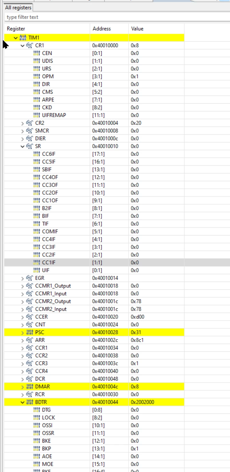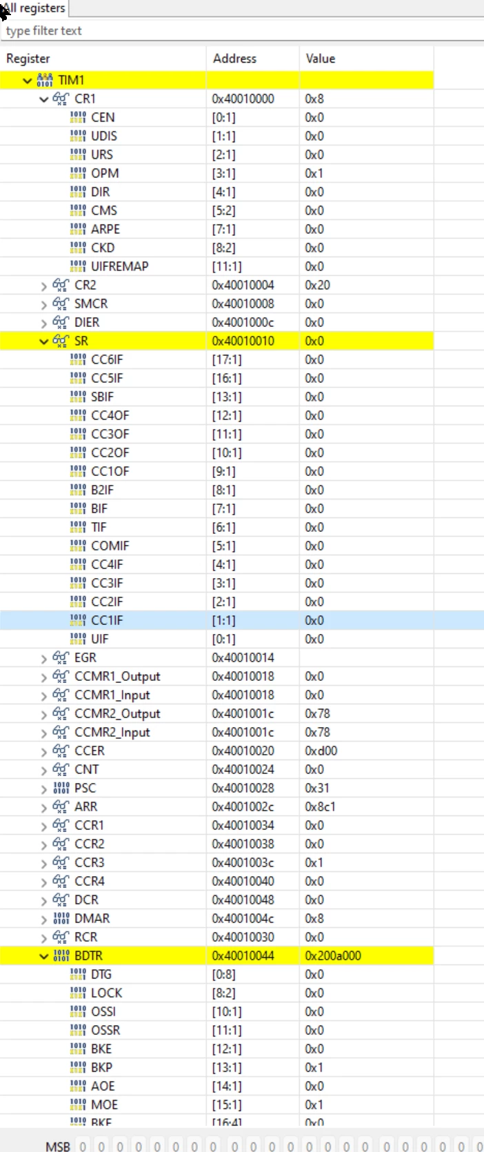
STM32H7B3I Timer 1 - Software intiated One Pulse Mode
Hi,
I wish to produce a single pulse; lo-Hi delay Hi to Low.
I am using Timer 1 PB15 which is the complementary output timer Channel 3
I am using the timer in the following sequence
- Timer initialisation
- Set the ARR and CCR3 with the following
ARR = 2241 (CCR4 + 1)
CCR4 = 2240 - I execute => HAL_TIM_PWM_Start_IT(&htim1, TIM_CHANNEL_3);
- Interrupt handler stops the timer => HAL_TIM_PWM_Stop_IT(&htim1, TIM_CHANNEL_3);
The correct width pulse is produced.
However if I don't use the interrupt to stop the timer the timer does not set the
output to reset state when the interrupt is initiated.
Thus the duration of the pulse produced is contingent upon the interrupt "clearing" the timer output PB15.
I do not want to use interrupts to produce the pulse as I want the pulse width to be accurate with very little jitter.
I have tried a heap of different configs to solve the problem and have been on stack exchange and this forum, but I can't figure out what I'm doing wrong.
Here is my code for the timer initialisation:
TIM_HandleTypeDef htim1;

/** IMPULSE TIMER
 *
 * @brief TIM1 Initialization Function
 * @PAram None
 * @retval None
 */
void MX_TIM1_Init(void)
{
 /* TIM1 clock enable */
 __HAL_RCC_TIM1_CLK_ENABLE();
 TIM_ClockConfigTypeDef sClockSourceConfig = {0};
 TIM_MasterConfigTypeDef sMasterConfig = {0};
 TIM_OC_InitTypeDef sConfigOC = {0};
 TIM_BreakDeadTimeConfigTypeDef sBreakDeadTimeConfig = {0};

 htim1.Instance = TIM1;
 htim1.Init.Prescaler = TIM1_PRESCALER - 1;
 htim1.Init.CounterMode = TIM_COUNTERMODE_UP;
 htim1.Init.Period = 2;
 htim1.Init.ClockDivision = TIM_CLOCKDIVISION_DIV1;
 htim1.Init.RepetitionCounter = 0;
 htim1.Init.AutoReloadPreload = TIM_AUTORELOAD_PRELOAD_DISABLE;
 if (HAL_TIM_Base_Init(&htim1) != HAL_OK)
 {
 Error_Handler();
 }

 sClockSourceConfig.ClockSource = TIM_CLOCKSOURCE_INTERNAL;
 if (HAL_TIM_ConfigClockSource(&htim1, &sClockSourceConfig) != HAL_OK)
 {
 Error_Handler();
 }

 if (HAL_TIM_PWM_Init(&htim1) != HAL_OK)
 {
 Error_Handler();
 }

 if (HAL_TIM_OnePulse_Init(&htim1, TIM_OPMODE_SINGLE) != HAL_OK)
 {
 Error_Handler();
 }

 sMasterConfig.MasterOutputTrigger = TIM_TRGO_UPDATE;
 sMasterConfig.MasterOutputTrigger2 = TIM_TRGO_UPDATE;
 sMasterConfig.MasterSlaveMode = TIM_MASTERSLAVEMODE_DISABLE;
 if (HAL_TIMEx_MasterConfigSynchronization(&htim1, &sMasterConfig) != HAL_OK)
 {
 Error_Handler();
 }

 sConfigOC.OCMode = TIM_OCMODE_PWM1;
 sConfigOC.Pulse = 1;
 sConfigOC.OCPolarity = TIM_OCPOLARITY_HIGH;
 sConfigOC.OCNPolarity = TIM_OCNPOLARITY_HIGH;
 sConfigOC.OCFastMode = TIM_OCFAST_DISABLE;
 sConfigOC.OCIdleState = TIM_OCIDLESTATE_RESET;
 sConfigOC.OCNIdleState = TIM_OCNIDLESTATE_RESET;
 if (HAL_TIM_PWM_ConfigChannel(&htim1, &sConfigOC, TIM_CHANNEL_3) != HAL_OK)
 {
 Error_Handler();
 }

 sBreakDeadTimeConfig.OffStateRunMode = TIM_OSSR_DISABLE;
 sBreakDeadTimeConfig.OffStateIDLEMode = TIM_OSSI_DISABLE;
 sBreakDeadTimeConfig.LockLevel = TIM_LOCKLEVEL_OFF;
 sBreakDeadTimeConfig.DeadTime = 0;
 sBreakDeadTimeConfig.BreakState = TIM_BREAK_DISABLE;
 sBreakDeadTimeConfig.BreakPolarity = TIM_BREAKPOLARITY_HIGH;
 sBreakDeadTimeConfig.BreakFilter = 0;
 sBreakDeadTimeConfig.Break2State = TIM_BREAK2_DISABLE;
 sBreakDeadTimeConfig.Break2Polarity = TIM_BREAK2POLARITY_HIGH;
 sBreakDeadTimeConfig.Break2Filter = 0;
 sBreakDeadTimeConfig.AutomaticOutput = TIM_AUTOMATICOUTPUT_DISABLE;
 if (HAL_TIMEx_ConfigBreakDeadTime(&htim1, &sBreakDeadTimeConfig) != HAL_OK)
 {
 Error_Handler();
 }

 /* Set the complementary output for Ch 3 active Polarity High*/
 htim1.Instance->CCER = 0xd00;
 HAL_TIM_MspPostInit(&htim1);

 HAL_NVIC_SetPriority(TIM1_UP_IRQn, 5, 0);
 HAL_NVIC_EnableIRQ(TIM1_UP_IRQn);

}

void HAL_TIM_PWM_MspInit(TIM_HandleTypeDef* tim_pwmHandle)
{

 if(tim_pwmHandle->Instance==TIM1)
 {
 /* USER CODE BEGIN TIM1_MspInit 0 */

 /* USER CODE END TIM1_MspInit 0 */
 /* TIM1 clock enable */
 __HAL_RCC_TIM1_CLK_ENABLE();

 /* TIM1 interrupt Init */
 HAL_NVIC_SetPriority(TIM1_UP_IRQn, 5, 0);
 HAL_NVIC_EnableIRQ(TIM1_UP_IRQn);
 /* USER CODE BEGIN TIM1_MspInit 1 */

 /* USER CODE END TIM1_MspInit 1 */
 }
}
void HAL_TIM_MspPostInit(TIM_HandleTypeDef* timHandle)
{

 GPIO_InitTypeDef GPIO_InitStruct = {0};
 if(timHandle->Instance==TIM1)
 {
 __HAL_RCC_GPIOB_CLK_ENABLE();
 /**TIM1 GPIO Configuration
 PB15 ------> TIM1_CH3N
 */
 GPIO_InitStruct.Pin = PB15_ImpulseOut_Pin;
 GPIO_InitStruct.Mode = GPIO_MODE_AF_PP;
 GPIO_InitStruct.Pull = GPIO_NOPULL;
 GPIO_InitStruct.Speed = GPIO_SPEED_FREQ_VERY_HIGH;
 GPIO_InitStruct.Alternate = GPIO_AF1_TIM1;
 HAL_GPIO_Init(PB15_ImpulseOut_GPIO_Port, &GPIO_InitStruct);
 }
}
Here is the code to initiate a pulse:
__inline void impulseGen(const float pulseWidth_ms)
{

	uint16_t pulseWidthCount;

	pulseWidthCount	= (uint16_t)(ms_to_count_tim1 * pulseWidth_ms);

	htim1.Instance->ARR = (uint32_t)(pulseWidthCount + 1);
	htim1.Instance->CCR3 = pulseWidthCount;

	HAL_TIM_PWM_Start_IT(&htim1, TIM_CHANNEL_3);

	/* Enable the TIM Update interrupt */
	__HAL_TIM_ENABLE_IT(&htim1, TIM_IT_UPDATE);
	triggerLED_Start(200, IMP_LED_BLUE, false);
}
In the RM0455 Rev 10 pp1469/2967 it says:
"Let’s say one want to build a waveform with a transition from ‘0’ to ‘1’ when a compare
match occurs and a transition from ‘1’ to ‘0’ when the counter reaches the auto-reload
value. To do this PWM mode 2 must be enabled by writing OC1M=111 in the
TIMx_CCMR1 register. Optionally the preload registers can be enabled by writing
OC1PE=’1’ in the TIMx_CCMR1 register and ARPE in the TIMx_CR1 register. In this
case one has to write the compare value in the TIMx_CCR1 register, the auto-reload
value in the TIMx_ARR register, generate an update by setting the UG bit and wait for
external trigger event on TI2. CC1P is written to ‘0’ in this example."
I states that the output should transition from 1 to 0 when the counter reaches the ARR.
I tried PWM2 with various combinations of output polarity, but I cannot get it to do the end of pulse transition without the interrupt initiated time stop function.
What am I doing wrong?