

STM32F7 Full Duplex SPI Slave - Daisy Chain with Shared Buffer
I'm currently working on a device that acts as a slave on a SPI bus, with the intention of being daisy-chained with a number of other devices. The bus master sends out a stream of data with 3 bytes meant for each slave, so the total number of bytes is [3 x Number of Slaves]. See below for a generalized image of the daisy-chain setup.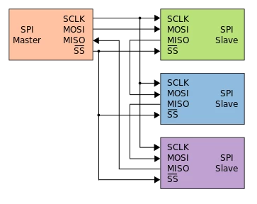
So far, I've had some limited success by initiating a DMA transaction using the same buffer with offset pointers. Because the transaction is an arbitrary length, I attach an interrupt to the hardware NSS pin rising edge and act on the data before resetting the DMA and SPI. Note that in the snippet below, I'm not doing anything with the data, simply resetting the bus.
static volatile uint8_t buf[128] = { 0 };

#define SPI_MAX_BYTES 125 // Buffer size - 3, due to RX pointer offset

void HAL_GPIO_EXTI_Callback(uint16_t GPIO_Pin)
{
 reset_spi_and_dma();
}

int main(void)
{
 SCB_EnableICache();

 HAL_Init();

 SystemClock_Config();
  MX_GPIO_Init();
 MX_DMA_Init();
 MX_SPI1_Init();

 HAL_SPI_TransmitReceive_DMA(&hspi1, buf, buf + 3, SPI_MAX_BYTES);

 while (1) { }
}

// Global interrupt clear flags for DMA streams
#define DMA_FLAG_GL0_4 0x0000003DU
#define DMA_FLAG_GL1_5 0x00000F40U
#define DMA_FLAG_GL2_6 0x003D0000U
#define DMA_FLAG_GL3_7 0x0F400000U

void reset_spi_and_dma(void)
{
	// Clear pending interrupt flags for DMA2 Stream 0 and Stream 3
	DMA2->LIFCR = DMA_FLAG_GL0_4 | DMA_FLAG_GL3_7;

	// Disable the DMA
	__HAL_DMA_DISABLE(&hdma_spi1_rx);
	__HAL_DMA_DISABLE(&hdma_spi1_tx);

	// Disable SPI1 peripheral
	__HAL_SPI_DISABLE(&hspi1);

	// Disable SPI1 DMA on RX and TX
	CLEAR_BIT(hspi1.Instance->CR2, SPI_CR2_RXDMAEN | SPI_CR2_TXDMAEN);

	// Set NDTR (DMA_SxNDTR) to the number of bytes to transfer
	hdma_spi1_rx.Instance->NDTR = SPI_MAX_BYTES;
	hdma_spi1_tx.Instance->NDTR = SPI_MAX_BYTES;

	// Reset SPI2 and clear TXFIFO
	RCC->APB2RSTR |= RCC_APB2RSTR_SPI1RST;
	RCC->APB2RSTR &= ~RCC_APB2RSTR_SPI1RST;

	// Reinitialize SPI1
	MX_SPI1_Init();

	// Reenable DMA
	__HAL_DMA_ENABLE(&hdma_spi1_rx);
	__HAL_DMA_ENABLE(&hdma_spi1_tx);

	// Enable SPI1 DMA on RX and TX
	SET_BIT(hspi1.Instance->CR2, SPI_CR2_RXDMAEN | SPI_CR2_TXDMAEN);

	// Reenable SPI1
	__HAL_SPI_ENABLE(&hspi1);
}
DMA for RX and TX on SPI1 are configured as circular with a data width of 1 byte. FIFO is disabled as my understanding is that adds latency to the DMA transaction for single byte transfers.
My understanding of how this should work is:
- NSS goes low and the hardware SPI transaction starts
- Data is clocked out on the rising clock edge from the TX pointer (buf[0])
- Data is clocked in on a falling clock edge to the RX pointer (buf[3])
- TX and RX pointers are incremented (to buf[1] and buf[4] respectively)
- This process repeats until NSS goes high and we manually stop/reset the peripherals
While this does somewhat work, it appears that the TX lags the RX by a full transaction. If I break the code after the first transaction, I see that buf is filled with the data as expected (confirmed with logic analyzer) but only 0x00 was shifted out for each clock cycle. Another transaction results in new data shifted in to buf but the data shifted out is what was in the buffer previously.
As an example, we see the following
Transaction 1)
Master MOSI: 0x01, 0x02, 0x03, 0x04, 0x05, 0x06
Slave MISO: 0x00, 0x00, 0x00, 0x00, 0x00, 0x00
[buf state after transaction = { 0x00, 0x00, 0x00, 0x01, 0x02, 0x03... }]
Transaction 2)
Master MOSI: 0x07, 0x08, 0x09, 0x0A, 0x0B, 0x0C
Slave MISO: 0x00, 0x00, 0x00, 0x01, 0x02, 0x03
[buf state after transaction = { 0x00, 0x00, 0x00, 0x07, 0x08, 0x09... }]
It almost seems like it's not actually operating on the memory pointers for TX and RX and is instead buffering data up prior to the transaction starting somehow, and only committing new data back to the buffer after the transaction is finished. Digging through the reference manual and looking at the HAL code didn't seem to point me in any obvious directions.
Is what I'm trying to do feasible? And if so, is there something I'm missing with configuration of the DMA to allow this to happen? Happy to offer any more information about the HAL configuration or any other relevant information.
