

Problem with a Timer DMA Burst mode
NUCLEO-F103RB with STM32F103RB
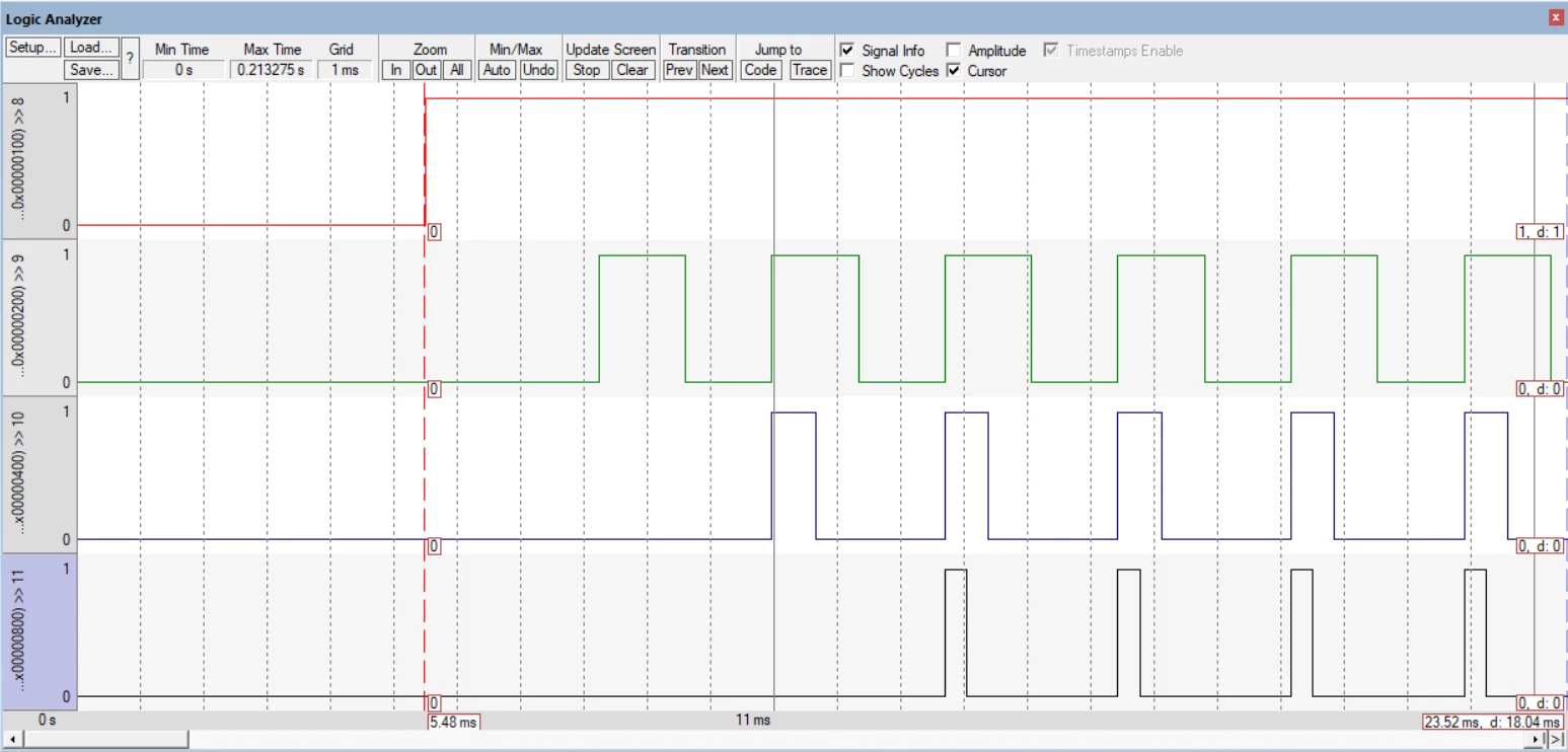
I want to use the DMA in a burst mode to write data from buffer in RAM to the TIM1_CCR1,2,3,4? that are in PWM mode. DMA burst transaction is requested on the TIM1 Update (UEV). Number of transactions in Burst mode is set to 4 transactions. According to the Reference Manual on each DMA Burst request 4 values from the buffer in RAM have to be transfered simultaneously to the CCR1,2,3,4. What I actually see is that on each TIM1 Update Event ONLY ONE TIM1_CCRx register is getting updated with a new value from the buffer.
Is that how it sappose to work, and if not where can be a problem?
IDE: arm Keil microVision5
Driver: STMicroelectronics SPL
Sourse code
#define TIM1_DMAR_ADDRESS ((uint32_t)0x40012C4C)
GPIO_InitTypeDef GPIO_InitStructure;
DMA_InitTypeDef DMA_InitStructure;
TIM_TimeBaseInitTypeDef TIM_TimeBaseStructure;
TIM_OCInitTypeDef TIM_OCInitStructure;
uint16_t SRC_Buffer[] = {0xFFFF, 0x7FFF, 0x3FFF, 0x1FFF};
int main(void)
{
RCC_APB2PeriphClockCmd(RCC_APB2Periph_GPIOA | RCC_APB2Periph_TIM1 , ENABLE);
RCC_AHBPeriphClockCmd(RCC_AHBPeriph_DMA1, ENABLE);
GPIO_InitStructure.GPIO_Pin = GPIO_Pin_8 | GPIO_Pin_9 | GPIO_Pin_10 | GPIO_Pin_11;
GPIO_InitStructure.GPIO_Mode = GPIO_Mode_AF_PP;
GPIO_InitStructure.GPIO_Speed = GPIO_Speed_50MHz;
GPIO_Init(GPIOA, &GPIO_InitStructure);
DMA_DeInit(DMA1_Channel5);
DMA_InitStructure.DMA_PeripheralBaseAddr = (uint32_t)TIM1_DMAR_ADDRESS;
DMA_InitStructure.DMA_MemoryBaseAddr = (uint32_t)SRC_Buffer;
DMA_InitStructure.DMA_DIR = DMA_DIR_PeripheralDST;
DMA_InitStructure.DMA_BufferSize = 4;
DMA_InitStructure.DMA_PeripheralInc = DMA_PeripheralInc_Disable;
DMA_InitStructure.DMA_MemoryInc = DMA_MemoryInc_Enable;
DMA_InitStructure.DMA_PeripheralDataSize = DMA_PeripheralDataSize_HalfWord;
DMA_InitStructure.DMA_MemoryDataSize = DMA_MemoryDataSize_HalfWord;
DMA_InitStructure.DMA_Mode = DMA_Mode_Normal;
DMA_InitStructure.DMA_Priority = DMA_Priority_High;
DMA_InitStructure.DMA_M2M = DMA_M2M_Disable;
DMA_Init(DMA1_Channel5, &DMA_InitStructure);
//TIM1 (PWM Generator)
TIM_DeInit(TIM1);
TIM_TimeBaseStructure.TIM_Period = 0xFFFF;
TIM_TimeBaseStructure.TIM_Prescaler = (uint16_t) (SystemCoreClock / 24000000)-1;
TIM_TimeBaseStructure.TIM_ClockDivision = 0x0;
TIM_TimeBaseStructure.TIM_CounterMode = TIM_CounterMode_Up;
TIM_TimeBaseInit(TIM1, &TIM_TimeBaseStructure);
TIM_OCInitStructure.TIM_OCMode = TIM_OCMode_PWM1;
TIM_OCInitStructure.TIM_OutputState = TIM_OutputState_Enable;
TIM_OCInitStructure.TIM_Pulse = 0x0000;
TIM_OC1Init(TIM1, &TIM_OCInitStructure);
TIM_OC1PreloadConfig(TIM1, TIM_OCPreload_Enable);
TIM_OC2Init(TIM1, &TIM_OCInitStructure);
TIM_OC2PreloadConfig(TIM1, TIM_OCPreload_Enable);
TIM_OC3Init(TIM1, &TIM_OCInitStructure);
TIM_OC3PreloadConfig(TIM1, TIM_OCPreload_Enable);
TIM_OC4Init(TIM1, &TIM_OCInitStructure);
TIM_OC4PreloadConfig(TIM1, TIM_OCPreload_Enable);
TIM_DMAConfig(TIM1, TIM_DMABase_CCR1, TIM_DMABurstLength_4Transfers);
TIM_DMACmd(TIM1, TIM_DMA_Update, ENABLE);
TIM_Cmd(TIM1, ENABLE);
TIM_CtrlPWMOutputs(TIM1, ENABLE);
DMA_Cmd(DMA1_Channel5, ENABLE);
while(1){}
}
Here is the picture I get in Keil's Logic Analyser
I'm using simulator now and in a long time will not be able to test program on a real MCU.
