

MSzal.1
Associate II
November 18, 2021
Solved

Is it possible to use USART RX/TX legs to blink a led?

  • November 18, 2021
  • 9 replies
  • 4236 views

Hello!

I have an STM32F411RE nucleoboard.

I tried to use PA2 (TX) and PA3 (RX) as a general output. I enabled the clock access and also setted the mode register to general purpose output mode, but when I connect the LED and set the pin high nothing happens. If I connect it to another pins e.g. PA0 (A0), PA1 (A1), PA8 (D7) it works fine. Could it be because the RX/TX legs can't be used as a general purpose output?

Thanks in advance for the help!

Best regards,

Martin0693W00000GY0PrQAL.png
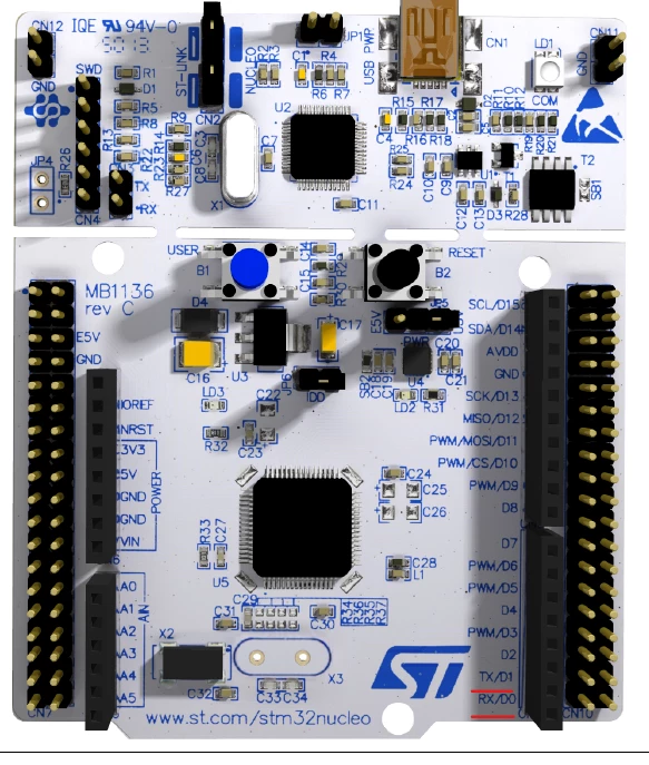
    This topic has been closed for replies.
    Best answer by Mike_ST

    As I said before don't forget to close SB62 and SB63 too, just a bit of tin between the pads will do the job.

    9 replies

    Mike_ST
    ST Technical Moderator
    November 18, 2021

    Hello,

    PA2/PA3 can be used as GPIO, but you have to remove SB14 and SB13 to disconnect them from the ST-Link UART interface.

     + check that SB62 and SB63 are set.

    In order to give better visibility on the answered topics, please click on 'Best answer' on the reply which solved your issue or answered your question. 
    MSzal.1
    MSzal.1Author
    Associate II
    November 18, 2021

    Sorry for this dumb question. Could You show me on the pictures which solder bridge should I remove? I checked the datasheet and I found SB13 and SB14 but I can't see where it joins. I attached 3 pictures about the board.

    Thank You! :)0693W00000GY3oLQAT.jpg0693W00000GY3o6QAD.jpg0693W00000GY3ofQAD.jpg

    Mike_ST
    ST Technical Moderator
    November 18, 2021

    I can't show you with your pictures, because it is on the other side of the board.

    In UM1724 page 14 Figure 4 "Bottom layout", they are shown.

    https://www.st.com/resource/en/user_manual/um1724-stm32-nucleo64-boards-mb1136-stmicroelectronics.pdf

    In order to give better visibility on the answered topics, please click on 'Best answer' on the reply which solved your issue or answered your question. 
    S.Ma
    Principal
    November 18, 2021

    MCU Tx is output and input on stlink side, so if you can't mingle the solder bridge, that shpuld work.Make sute to program the pin as output push pull.

    MSzal.1
    MSzal.1Author
    Associate II
    November 18, 2021

    I checked the code it but still not works. The delay is from TIM2_CH1 (PA0). It1s interesting because it worked on PA1 and PA4.

    0693W00000GY48aQAD.png0693W00000GY48QQAT.png
