

Associate
April 8, 2025
Question

difference between real measured frequency and set frequency

  • April 8, 2025
  • 7 replies
  • 733 views

Hello,

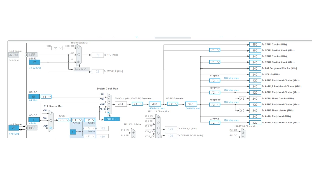
I am dealing with difference between real measured frequency and set on my Nucleo H755ZI-Q.
the measured real frequency :
APB1 76,8 MHz
APB2 76,8 MHz
recalculated
debugging frequencz SWV Core Clock 153,6 MHz

I also try printf debuged frequency:
HSE is enabled and ready.
System Clock: 480000000 Hz
APB1 Timer Clock: 120000000 Hz
APB2 Timer Clock: 120000000 Hz
APB1 Prescaler: 4
APB2 Prescaler: 4
PetrK_0-1744104643584.png

 if ((RCC->CR & RCC_CR_HSERDY) != 0) {
 printf("HSE is enabled and ready.\n");
 } else {
 printf("HSE is not enabled or ready.\n");
 }

 printf("System Clock: %lu Hz\n", HAL_RCC_GetSysClockFreq());
 printf("APB1 Timer Clock: %lu Hz\n", HAL_RCC_GetPCLK1Freq());
 printf("APB2 Timer Clock: %lu Hz\n", HAL_RCC_GetPCLK2Freq());


 uint32_t apb1_prescaler = (RCC->D2CFGR & RCC_D2CFGR_D2PPRE1) >> RCC_D2CFGR_D2PPRE1_Pos;
 uint32_t apb2_prescaler = (RCC->D2CFGR & RCC_D2CFGR_D2PPRE2) >> RCC_D2CFGR_D2PPRE2_Pos;

 printf("APB1 Prescaler: %lu\n", apb1_prescaler);
 printf("APB2 Prescaler: %lu\n", apb2_prescaler);

 uint32_t pclk1 = HAL_RCC_GetPCLK1Freq(); // Get APB1 clock
 uint32_t pclk2 = HAL_RCC_GetPCLK2Freq(); // Get APB2 clock

 printf("APB1 Clock: %lu Hz\n", pclk1);
 printf("APB2 Clock: %lu Hz\n", pclk2);

 // If prescaler > 1, Timer Clock = PCLK * 2
 if (apb1_prescaler > 3) { // Values >3 mean prescaler is applied
 printf("APB1 Timer Clock: %lu Hz\n", pclk1 * 2);
 } else {
 printf("APB1 Timer Clock: %lu Hz\n", pclk1);
 }

 if (apb2_prescaler > 3) {
 printf("APB2 Timer Clock: %lu Hz\n", pclk2 * 2);
 } else {
 printf("APB2 Timer Clock: %lu Hz\n", pclk2);
 }
 
Does anyone have any suggestion what I am doing wrong?

Edited Code Format 


This topic has been closed for replies.

7 replies

ST Employee
April 8, 2025

Hello @PetrK, 

Given that the discrepancy is huge, in the order of 50MHz for APB1 and APB2, i suspect there is maybe an issue with the measurement method! 

To give better visibility on the answered topics, please click on Accept as Solution on the reply which solved your issue or answered your question.
PetrKAuthor
Associate
April 8, 2025

Hello @Sarra.S ,

thank you for the reply, I think that it is not measurement method - also have to set the timers regarding to the value ato be able run the servos. The real frequency is real.
I also have to add the 153.6 MHz into the SWV settings to get the printf values.  

PetrK_0-1744109072196.png

Should it be some power issue? I am powering the Nucleo

through USB from notebook.

MasterT
Lead II
April 8, 2025

In case of ambiguity, use hardware - oscilloscope verification driving MCO1 / MCO2 outputs, there 5 /6 control check points for each

ST Employee
April 10, 2025

Hello @PetrK, any updates on this matter? 

To give better visibility on the answered topics, please click on Accept as Solution on the reply which solved your issue or answered your question.
PetrKAuthor
Associate
April 14, 2025

Hello,
I goes through the user manual once again and realize that the inputed HSE frequency is provided by ST LINK MCO - 8 Mhz. There was set authomaticly 25 Mhz in the clock configuration. 

https://www.st.com/resource/en/user_manual/um2408-stm32h7-nucleo144-boards-mb1363-stmicroelectronics.pdf
7.9.1

I followed tutorial paths for set HSE, but nobody mentioned, that it is necessary to improve the solder bridges on the board to connect the external oscillator. This is my first STM32 board, so I do not know if it is standard or something special for my H7 version.


.  

MasterT
Lead II
April 14, 2025

" I followed tutorial paths for set HSE, but nobody mentioned, that it is necessary to improve the solder bridges on the board to connect the external oscillator. This is my first STM32 board, so I do not know if it is standard or something special for my H7 version. "

What kind of tutorial ?

Nucleo working as it is, AFAIK ST-Link always provides clock on any nucleo boards, with option 8 or 8.33 MHz.

No hardware re-config required. Simply enter 8 MHz into box instead of 25.  Likely software StmCubeMX bug or you start project in another way - from uCPU selector instead of board selector.